11
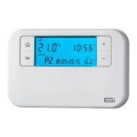
6. The programmer display will show symbol when it is
able to receive signal and symbol when it is unable
to receive signal.
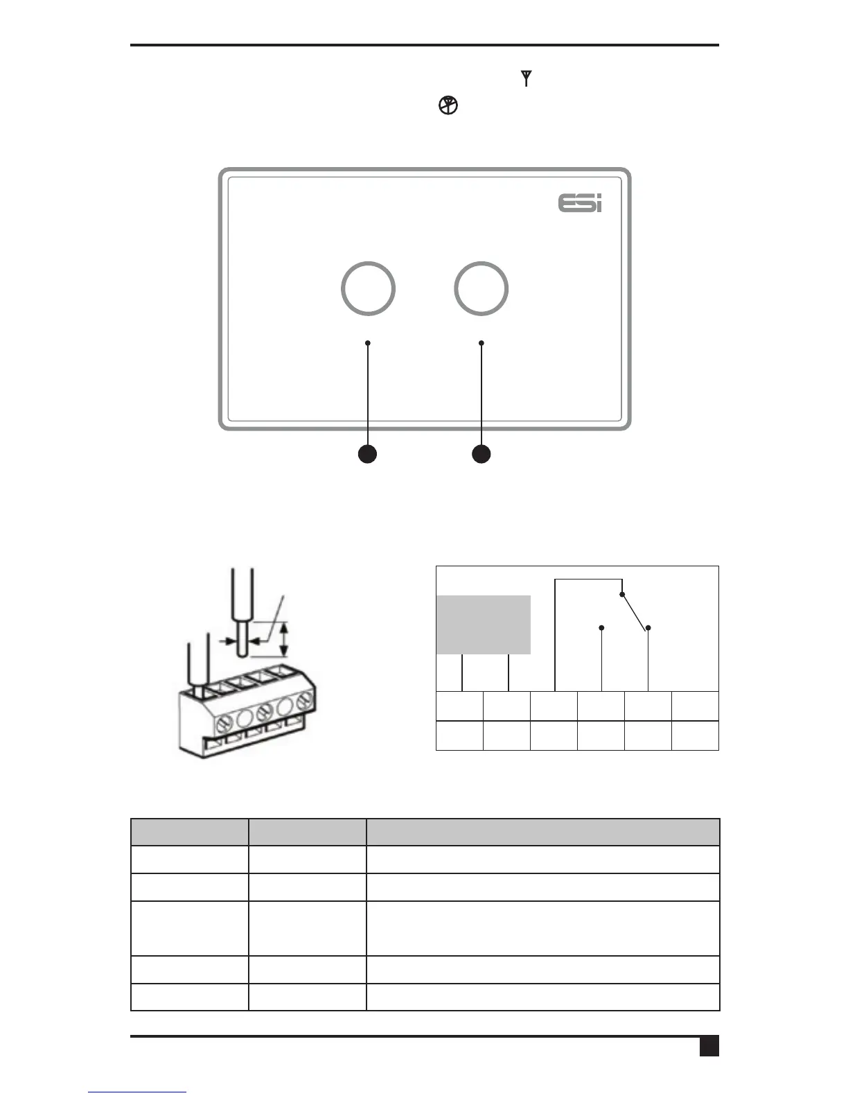
2.9 Wiring diagram
Programmable Room Thermostat Receiver
M/A MANUAL
1 2
1.0-2.5mm
2
6mm MAX
N L 1 2 3 4
COM N/O N/C
Fused Main
Supply
N.B. Volt free contacts.
Terminal Identifier Description
N Neutral Neutral
L Live Live Feed (230V AC)
1 COM
Linked Live Feed (230V AC Heating
Applications Only)
2 N/O Normally open
3 N/C Normally closed (NC)
 Loading...