- 18 -
- If the need is beyond the capacity of the pump A, pump B is activated. Both pumps sync speed to meet
demand (exchange rate set according to menu 10.4)
- If the need exceeds the capacity of the pumps A + B, the pump C is activated. Three pumps sync speed to
meet demand.
- And successively...
The operation mode is alternated. For each activation of the booster set, the order of start pumps is random. This
will equal the operation hours.
Installation and connections.
Installation and connections.Installation and connections.
Installation and connections.
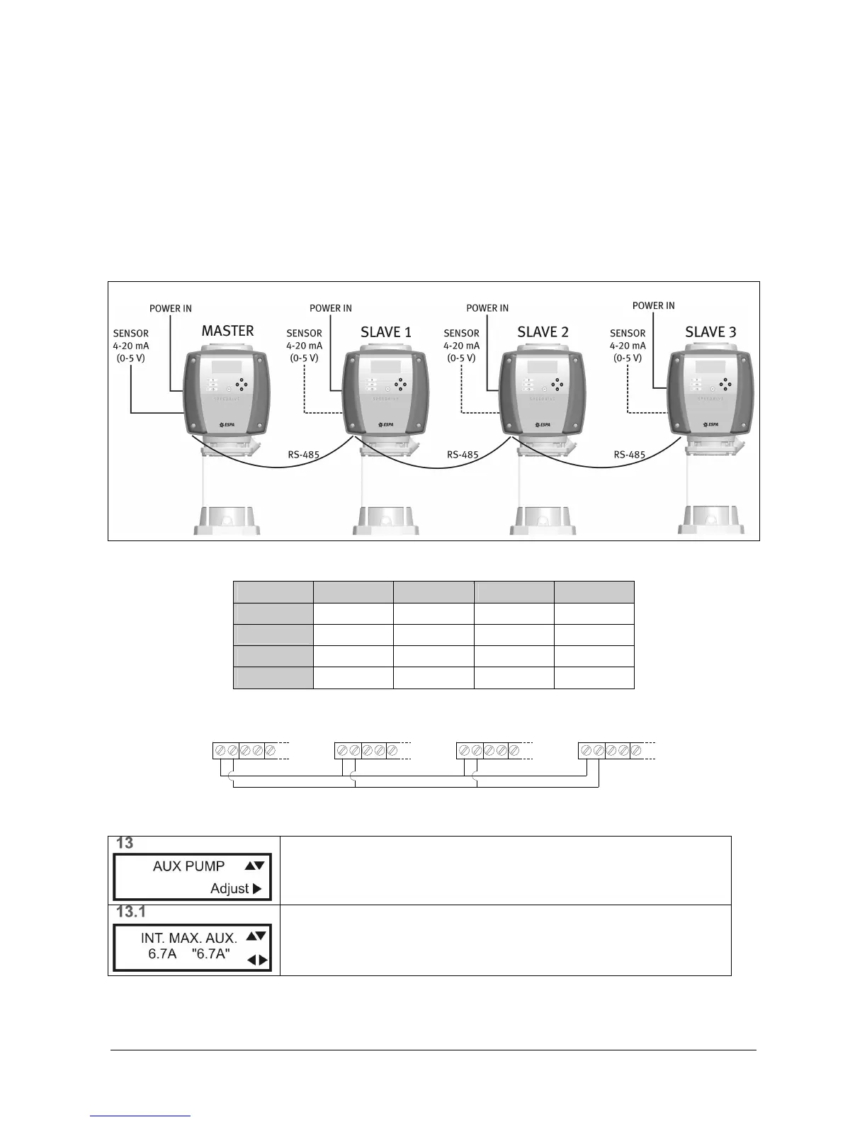
The Speedrive installation and electrical wiring is done as described in this manual.
The connection of the pressure transducer must be made solely on the "Master" Speedrive.
A 2-wire twisted and shielded cable 0.5mm2 section must make the communication between devices.
Configuration.
Configuration. Configuration.
Configuration.
Set master Speedrive menus as follows:
AUXILIAR
AUXILIARAUXILIAR
AUXILIARY PUMP
Y PUMPY PUMP
Y PUMP
Press ► (Adjust) for the adjustment of the parameters that govern to the
auxiliary pumps.
Ignore. Press ▼