Do you have a question about the ESPEC SU Series and is the answer not in the manual?
Details environmental and physical conditions for chamber installation.
Step-by-step guide on how to install and level the chamber.
Explains the drainage system, hose connections, and important notices for proper drainage.
Outlines voltage, current, cable size, and fuse capacity requirements for power supply.
Details safe connection procedures and essential grounding instructions.
Procedure for filling the water supply tank with appropriate water.
Procedure for transferring water from the tank to the humidifying tray.
Guide to setting temperature and humidity targets and inputting them into the system.
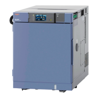
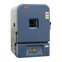
This document serves as an installation guide for the ESPEC bench-top type temperature (and humidity) chamber, specifically models SH and SU. It outlines the necessary steps for bringing in and installing the chamber, emphasizing safety precautions and proper handling to prevent accidents or equipment damage. Users are advised to read the entire manual thoroughly before commencing any work.
The ESPEC bench-top type temperature (and humidity) chamber is designed to create controlled environments for testing various specimens. It can regulate temperature and, for SH models, humidity, making it suitable for a range of research, development, and quality control applications. The chamber's primary function is to subject specimens to specific environmental conditions to observe their behavior and performance.
The chamber is intended for use by experienced engineers or trained personnel who understand its purpose, operation methods, and daily maintenance. This ensures safe and effective operation, mitigating risks associated with electrical components and other potential hazards.
The manual employs a clear system of safety indications to highlight potential dangers:
ESPEC is committed to eco-friendly product development, adhering to guidelines for preventing global warming and pollution, and promoting resource recycling. Products intended for the Japanese market that meet specific energy-saving criteria receive the “GREEN PRODUCT Label,” which is equivalent to the ISO Type II environmental label. To qualify, a product must achieve more than 15% energy savings in power consumption compared to its former model, based on ESPEC's specified operation patterns. The manual also provides "Energy Saving Advice" to help users operate the chamber efficiently.
Proper installation is crucial for the chamber's performance and safety. The chamber must be installed indoors on a flat, level floor capable of supporting its weight. The site should have minimal mechanical vibrations, be free from airborne contaminants, and be dry. It should also be free from flammable materials, combustible or corrosive gases, and not exposed to direct sunlight. Good ventilation is essential, and the ambient temperature should be between +5°C and +35°C, with a maximum humidity of 75% RH (+23°C being optimal). The ambient temperature should not fluctuate by more than 5°C within a few minutes. The chamber should not be placed directly under a fire alarm or near high-temperature heat sources. Proximity to power, water, and drainage utilities is also recommended. The installation altitude should not exceed 1000m. Operating the chamber outside these specified ambient temperature ranges may lead to malfunction.
When moving the chamber, extreme caution is advised to prevent fingers from being caught or the chamber from falling. If using a forklift, ensure the front ends of the forks are not covered by the chamber. The manual provides a diagram illustrating the center of gravity positions for different models to aid in safe handling.
The chamber is equipped with leveling feet under each of its four corners. To install, users must turn the adjustable feet until the chamber sits level. A level should then be placed on the center of the test area floor to verify the levelness. This is critical because an unlevel chamber can cause water to backflow, leading to drainage issues, false alarms, and destabilized humidity control. The chamber should never be moved with specimens inside, as they may tip over or fall.
For export models, the chamber door is secured with a retainer during shipping to prevent accidental opening. After installation, this retainer and any moisture absorbents must be detached.
The manual includes a comprehensive list of accessories and spare parts provided with the chamber, such as shelves, cable port rubber plugs, humidifying tray drain hoses, water tank level sensor tank drain hoses, connectors, terminal plugs, power plugs, wet-bulb wicks, cartridge fuses, Class CC fuses, breaker handle covers, stylus pens, operation manuals, and warranty cards. Users are instructed to check if all items are included.
Drainage work is necessary to remove water from the humidifying tray and condensation from the test area. The chamber uses a gravitational drainage system, requiring the drain hose to be sloped downward to prevent stagnant water and direct it into a pit. The drain hose is located at the rear underneath the chamber. The drain tube is approximately 1m long with an O.D. of Ø18mm and an I.D. of Ø12mm.
The drain pipe from the chamber's rear panel should be connected to a drainage system or run into a container or pit. The drain pipe has an I.D. of Ø12 mm. When connecting, fit the hose over the nipple and press inward until a connection catch is heard.
Users are warned that hot water may drain from the humidifying tray shortly after operation, posing a burn risk. Caution is advised when handling hot water drainage. The manual identifies the water supply sensor container drain port (for cleaning the water supply pump filter) and the humidifying tray drain port (for temperature operation or cleaning the humidifying tray).
Primary power supply requirements must comply with national regulations. External power supply cables must be of an approved type and meet IEC/EN60227 or IEC/EN60245 standards. The manual provides a table detailing supply voltage ranges and advises keeping fluctuations within ±5%. It also specifies maximum current per voltage, minimum cable diameter, and fuse capacity.
When using a leakage breaker as the primary power switch, it must support high harmonics to prevent malfunctions. Grounding the equipment is mandatory to prevent electric shock from leakage current and protect against power supply noise, which can destabilize temperature and humidity control. Grounding on gas pipes is strictly prohibited due to explosion risk. The ground should not be shared with equipment not fitted with a leakage breaker, as the chamber's breaker will not trip for overcurrent, short-circuits, or surges in such cases.
The manual provides power cable color codes for different voltage specifications (100V/200V AC, 220V/230V AC, and 115V AC) for L phase, N phase, and GND connections. For SH/SU-222,242,262 models, the chamber is grounded through the power cable when plugged into an electrical outlet, eliminating the need for separate grounding. For 220 and 230V AC supplies, a specific plug type (CEE 7/7) is used, requiring a matching outlet. The chamber must be grounded with a maximum 100 Ω resistance against the ground.
To power on, first turn the circuit breaker ON (located on the right side of the chamber), then press the instrumentation power switch. To power off, press the instrumentation power switch, then turn the circuit breaker OFF. Users are advised to wait at least 20 seconds after turning the circuit breaker ON before turning it OFF again to protect the system.
For SH models, water for the humidifying tray is supplied from a water supply tank. Before filling the tank or cleaning the chamber, the door must be closed and remain closed to prevent injuries. Only pure water with a conductivity between 0.1 to 10µS/cm should be used; tap water or ultra-pure water can shorten the life of the humidifying heater and wet-bulb wick, or deform water circuit parts. The chamber should not be run with the water supply tank drawer open, as this can destabilize temperature and humidity control.
To supply water from the tank to the humidifying tray, the chamber must be run. The factory default setting is 0°C with humidity control OFF.
Water is supplied to both the humidifying tray and wick pan. For proper operation, the water level should be 4mm lower than the test area floor.
If the water level in the humidifying tray water level regulator is above or below the WATER LEVEL mark (indicating overflow or the heater sticking out), it may be due to improper tank connection, an unlevel chamber, or incorrect regulation.
For SH models, check that the water level in the regulator is at the WATER LEVEL mark. Before removing the humidifying tray water level regulator level check panel, shut OFF power at the main power switch to prevent injuries from the air circulator in the mechanical parts compartment.
| Humidity Range | 10% to 98% RH |
|---|---|
| Temperature Fluctuation | ±0.3°C |
| Temperature Gradient | ±1.0°C |
| Refrigerant | R-404A |
| Temperature Range | -20°C to +150°C |
| Power Supply | AC 200V, 220V, 230V, 240V, 50/60Hz |
| Temperature Uniformity | ±0.5°C |
| Heating Rate | 3°C/min |
| Cooling Rate | 1°C/min |
| Control System | Programmable controller |