Do you have a question about the EST SIGA-CC2A and is the answer not in the manual?
Introduces SIGA-CC2A/MCC2A modules, their function as intelligent analog addressable devices, and key features.
Lists key capabilities including Class A/B operation, dual input, ring-tone generator, auto mapping, electronic addressing, and ground fault detection.
Details personality codes (5, 27, 6, 28, 26, 29, 25, 19) for SIGA-CC2A/MCC2A when used as a single input module.
Details personality codes (7, 30) for SIGA-CC2A/MCC2A when used as a dual input module.
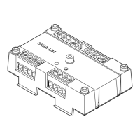
Covers installation procedures for SIGA-MCC2A on UIO motherboard and SIGA-CC2A in electrical boxes.
Explains how the loop controller electronically addresses each module, eliminating the need for physical switches.
Lists key warnings regarding riser supervision, detector compatibility, power dependency, and installation code compliance.
Specifies compatibility with Edwards EST3 control panels and Signature Series Loop Controller.
Details automatic self-diagnosis, user-friendly maintenance program, and scheduled maintenance requirements.
Illustrates wiring for SIGA-CC2A for various personality codes, including speaker and telephone circuits.
Shows wiring for SIGA-MCC2A on UIO motherboard for various personality codes, including speaker and telephone circuits.
Provides important notes on wire resistance, size, power limiting, and UIO6 module compatibility.
Details electrical parameters (voltage, current, impedance) and environmental conditions (temperature, humidity).
Describes mounting options and synchronization requirements per UL1971 standard.
Lists catalog numbers, descriptions, shipping weights for modules, related equipment, and accessories.
Details the strobe capacity of the modules based on different candela ratings.
| Operating Voltage | 24 VDC |
|---|---|
| Operating Temperature | 0 °C to 49 °C (32 °F to 120 °F) |
| Humidity | 93% non-condensing |
| Mounting | 4" (101.6 mm) square electrical box |
| Compatibility | EST3 |