Do you have a question about the EST SIGA-CRR and is the answer not in the manual?
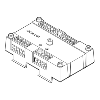
Describes the SIGA-CRR Polarity Reversal Relay Module and its function.
Explains the function of diagnostic LEDs for module status indication.
Details the personality code for configuring module operation.
General notes and precautions for installing the module.
Steps for physically mounting the module, including the wall plate.
Ensuring field wiring is free of opens, shorts, and ground faults.
Instructions and reference to the wiring diagram for connections.
Guidance on stripping wire ends for proper terminal connection.
Illustrates a common scenario for using the SIGA-CRR module.
Details operating voltage, current, and contact rating.
Information on SLC designation and compatible detector bases.
Specifications for electrical boxes and wire size.
Temperature and humidity ranges for the module.
Information about the manufacturer and EU representative.
Details FCC compliance and North American/European standards.
Certification details and WEEE directive information.
The SIGA-CRR Polarity Reversal Relay Module is an addressable device designed for use within fire alarm systems, specifically to power and activate audible sounders in Signature audible detector bases. This module integrates seamlessly into a signaling line circuit (SLC) and is capable of supporting a 2 A load of bases. Its primary function is to reverse the polarity of its 24 VDC output upon command from the loop controller, thereby activating the connected audible sounders.
The SIGA-CRR module operates as a crucial interface between the fire alarm control panel and audible sounder bases. It requires one address on the SLC, which is assigned electronically, eliminating the need for manual address switches. This electronic addressing simplifies installation and configuration.
The module's core functionality revolves around its ability to transfer a relay, which in turn reverses the polarity of its 24 VDC output. This polarity reversal is the mechanism by which the module activates the audible sounders in the detector bases. This allows for centralized control over the activation of multiple sounders according to system programming rules.
Beyond its primary role in activating sounder bases, the SIGA-CRR module can also be configured with a personality code to serve as a dry relay contact. When configured with personality code 8 (Signal - dry contact output), it can control external appliances such as door closers, fans, or dampers, or facilitate equipment shutdown in response to an alarm condition. This versatility allows the module to play a broader role in integrated building safety systems.
The SIGA-CRR module is designed for straightforward installation and integration into existing fire alarm systems. It is shipped as an assembled unit, meaning there are no user-serviceable parts, and it should not be disassembled. This simplifies the installation process and reduces the potential for errors.
For installation, the module is mounted on a wall plate, which is then attached to a compatible electrical box. Clear mounting details are provided to guide the installer. Wiring connections are made to a terminal block on the module, and it is crucial to ensure that all field wiring is free of opens, shorts, and ground faults before making connections. The module's terminals are designed to accommodate a single conductor.
The module incorporates diagnostic LEDs that provide visible indication of its operational state through the cover plate. A green LED flash indicates normal operation, while a red LED flash signifies an alarm or active state. These visual indicators allow for quick and easy status checks, aiding in troubleshooting and maintenance.
Configuration of the module's operational mode is achieved by downloading a personality code from the loop controller. This software-based configuration offers flexibility in how the module functions, allowing it to be tailored to specific system requirements. The ability to configure it as a dry relay contact for controlling external equipment expands its utility beyond just sounder activation.
While the SIGA-CRR module itself contains no user-serviceable parts, its design incorporates features that facilitate system maintenance and troubleshooting. The diagnostic LEDs are a key maintenance feature, providing immediate visual feedback on the module's status. This allows technicians to quickly identify if the module is operating normally or if an alarm condition is present, without needing specialized tools.
During installation, a label is provided for writing the module's assigned address, which is then applied to the module. Additionally, the serial number label is removed from the module and attached to the project documentation. This practice ensures accurate record-keeping, which is vital for future maintenance, system audits, and compliance checks. Proper documentation helps in quickly identifying and locating specific modules within a large system.
The module's robust design and lack of user-serviceable parts contribute to its reliability and reduce the need for frequent maintenance. The instruction to not disassemble the module emphasizes its sealed nature, which helps protect internal components from environmental factors and tampering.
Adherence to local codes, standards, and the authority having jurisdiction is a fundamental aspect of maintaining the system's integrity and ensuring its proper operation. The installation sheet emphasizes this, guiding installers to follow established guidelines for wiring and placement. This proactive approach to installation minimizes potential issues that could arise during the system's operational life.
Furthermore, the module's integration within a supervised signaling line circuit means that faults, such as opens or shorts in the wiring, can be detected by the loop controller. This supervision is a critical maintenance feature of the overall fire alarm system, as it ensures that any issues affecting the module's connectivity or power supply are promptly identified, allowing for timely corrective action. The requirement to strip wire ends to a precise length (1/4 inch or about 6 mm) is also a detail that contributes to reliable connections, preventing issues like ground faults or faulty connections that would otherwise require troubleshooting.
| Model | SIGA-CRR |
|---|---|
| Operating Voltage | 24 VDC |
| Contact Configuration | Form-C (SPDT) |
| Type | Control Relay |
| Compatibility | EST3 and EST3-X |
| Current Rating | 2 A @ 30 VDC (resistive) |
| Operating Temperature | 32°F to 120°F (0°C to 49°C) |
| Humidity Range | 0 to 93% RH, non-condensing |
| Function | Provides a dry contact interface to control a variety of auxiliary functions, such as elevator recall, door release, fan shutdown, etc. |