Abb. 3: Farbschema der Decoderkabel (DCC / Märklin®) // Wiring code for decoder wires (DCC / Märklin®)
21MTC PluX Next18 Hinweise (Notes) Name Märklin DCC
22 12 1, 18 TRACK1 rot schwarz
red black
21 14 9, 10 TRACK2 braun rot
brown red
19 8 2 MOTOR1 blau orange
blue orange
18 10 11 MOTOR2 grün grau
green gray
16 9 6 +24V(U+,pos.Terminal) orange blau
orange blue
7 13 17 REARLIGHT gelb gelb
yellow yellow
8 7 8 FRONTLIGHT grau weiß
gray white
15 16 3 OutputAUX1 braun/rot grün
brown/red green
14 18 12 OutputAUX2 braun/grün violett
brown/green purple
13 2 4 Logikausgang an 21MTC OutputAUX3 braun/gelb -
logic level on 21MTC brown/yellow -
4 19 13 Logikausgang an 21MTC OutputAUX4 braun/weiß -
logic level on 21MTC brown/white -
17 20 - Logikausgang an 21MTC OutputAUX5 braun/gelb -
logic level on 21MTC brown/yellow -
3 21 - Logikausgang an 21MTC OutputAUX6 braun/weiß -
logic level on 21MTC brown/white -
9
10
15
17
16
7
Speaker 1
Speaker 2
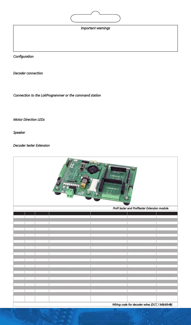
Abb. 2: Profi-Prüfstand und Profi-Prüfstand Extension // Profi tester and Profitester Extension module
Important warnings
•Thedecodertesterisexclusivelyintendedfortestingdecodersofmodeltrainlayouts.Itmayonlybeoperated
with the components listed here. Any other use is not permitted.
•Anywiringhastobecarriedoutwhilepowerisdisconnected.
•Adheretothewiringprinciplesasoutlinedhereforwiringanydecoderstothedecodertester.
•Keepdryandprotectitfrommechanicalshocks.
Configuration
The decoder tester is designed for testing or programming of decoders in combination with your digital command
station or ESU LokProgrammer before these are installed into a loco. Therefore, the decoder tester simulates all
needed elements usually seen in a locomotive. The decoder tester is equipped with all common interfaces.
Decoder connection
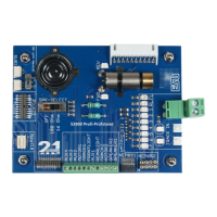
On the decoder tester, all items are labelled for your reference. Please select the appropriate interface first. Connect
one decoder to the tester at a time only. See figure 1 for details.
If you own a decoder without interface, you can connect the single wires to the screw terminal. Please note the
colour code that is different for DCC or Märklin. Figure 3 shows the details.
Connection to the LokProgrammer or the command station
The decoder tester has to be connected to the programming track output of your command station or the Lok-
Programmer. We supply a 2-pin, removable plug, that is first fixed below the decoder tester using a small piece of
tape for transport reasons. Remove the plug and connect it to the decoder tester as shown in figure 4. Then, add
two wires from the tester to the command station / LokProgrammer. If power is applied to the command station‘s
orLokProgrammer‘soutput,theLEDlabelled„TRACK“shouldlit.
Motor Direction LEDs
Next to the motor, you can find two LEDs. Based on the direction of travel, one of these should lit when the
motor is moving.
Speaker
IfyouwouldliketotestanoldLokSoundV3.5decoder,settheswitchto„100Ohms“.Otherwise,pickthe„16
Ohms“setting.Ifyoudon‘tlikethespeakeroutput,justswitchittoOFFposition.
Decoder tester Extension
If you want also test ESU Decoders for gauge 0 or G, you can connect the Decoder Tester Extension (ESU Item
number 53901) to your tester. Figure 2 shows how to connect it.
 Loading...