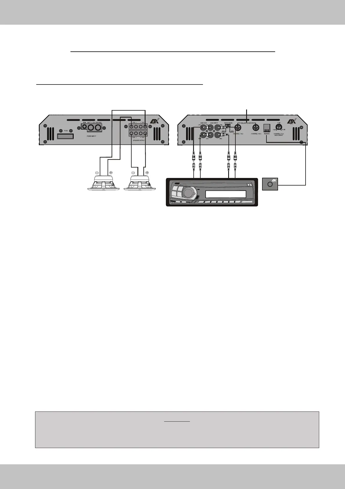
2-CHANNEL-MODE: 2 Subwoofers / Mono bridged
LOUDSPEAKER WIRING & CONNECTION
4-Channel Amplifier VE800.4 / VE1200.4
BALANCED INPUT CH 1&2 / CH 3&4
This Input can optionally be used with appropriate cables and
symmetrical signal transmitters. Please do not use this Input at
the same time as the RCA Inputs.
CONNECTIONS
• Connect the head unit line outputs (FRONT L & R and REAR L & R) with the RCA LINE INPUTs of the amplifier
with appropriate RCA cables.
• Connect subwoofer 1 with SPEAKER OUTPUT CH 2 – and CH 1 + and subwoofer 2 with SPEAKER OUTPUT
CH 4 – and CH3 + of the amplifier.
• The final speaker impedance should not be lower than 2 Ohm per Subwoofer.
CONFIGURATION SUBWOOFER 1 & 2
• T7 should be set to BAND PASS. The upper threshold frequency of the LOW PASS should be between
60Hz - 150Hz, depending on size of the subwoofer and is adjustable by T11. The lower threshold frequency
(Subsonicfilter) is adjustable by T12 (See page 32).
• When the Pushbuttons T9 & T10 are pressed, the slew rate of the frequency response is raised up to 24dB in
Mono mode (See page 32).
BASS BOOST & BASS REMOTE
• Both features should not be used in this configuration.
INPUT GAIN - Control
• Turn the INPUT GAIN - control (T6 & T8) on the amplifier to 9V-Position.
• Turn the head unit volume control to about 80-90% of ist full setting.
• Turn the INPUT GAIN - control (T6 & T8) clockwise until you hear some distortion.
• Then turn back the INPUT GAIN - control (T6 & T8) slightly until you can hear clean sound.
31
RADIO / HEAD UNIT
INPUT MODE
When you want to use 4 RCA
cabels Input mode switch (T5)
should be set on "4CH"-Position.
LINE OUT (F1)
Optional triggering to
use additional amplifiers.
4 OHMS
SUBWOOFER
4 OHMS
SUBWOOFER
Caution!
Be careful not to connect speaker (-) to the ground or vehicle chassis.
Please observe speaker channel and polarity as printed by the speaker terminal block.
Incorrect phasing of the speakers results in total loss of bass response.
BASS REMOTE
MIN - MAX Level Controller
White LED = Operation Mode
Red LED = Protection Mode
(see page 19)
MIN MAX
LEVEL