Congratulations on your purchase of this high-quality ESYLUX product. To ensure proper operation, please read
these user instructions carefully and keep them for future reference.
1 • SAFETY INSTRUCTIONS
CAUTION: Work on the 230 V power system must be carried out by authorised personnel only
with due regard to the applicable installation regulations. Switch off the power supply before
installing the system.
Use this product only as intended (as described in the user instructions). Changes or
modifications to the product or painting it will result in loss of warranty. You should check
the device for damage immediately after unpacking it. If there is any damage, you should
not install the device under any circumstances. If you suspect that safe operation of the
device cannot be guaranteed, you should turn the device off immediately and make sure
that it cannot be operated unintentionally.
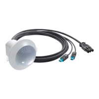
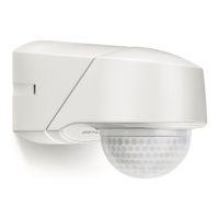
2 • DESCRIPTION
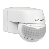
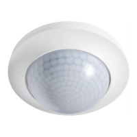
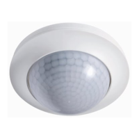
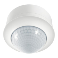
ESYLUX RCi series motion detectors have a 130°/230°/280° field of detection and 360°
creep zone protection. ESYLUX motion detectors are passive infrared detectors that react to
moving heat sources (people, vehicles) (fig. 1 (1) 360° creep zone protection (2) Facing detector
(3) Diagonal to detector). If the motion detector registers changes in the heat emissions within
its field of detection, depending on the set Lux level, it switches on the connected load
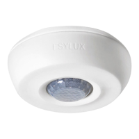
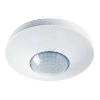
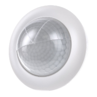
(e.g. lighting) for an adjustable length of time. The ESYLUX RCi motion detector series can
be mounted onto a wall or ceiling without the need for any further accessories.
A base is available to allow it to be mounted to an internal or external corner.
The ESYLUX RCi motion detector has a default programme allowing it to work within
predefined parameters (10 Lux, 2 minutes, max. electronic range). There are two different
ways of setting the detector – either conventionally using the setting controls on the device
itself, or using the convenient optional remote control, ESYLUX Mobil-RCi or Mobil-RCi-M.
NB: To activate all functions on the detector,
the remote control Mobil-RCi is required.
3 • INSTALLATION/MOUNTING/CONNECTION
Please observe the following points prior to fitting the device:
• The power supply must be disconnected prior to fitting.
• All data concerning the range presume an installation height of 2.50 m.
(If installed at a different height the values for the range will be affected).
• Best results (max. range) are achieved if the device is installed diagonally to the direction
of motion (fig. 1).
• Ensure that there are no obstacles between the area to be covered and the detector, as
infrared rays cannot penetrate solid matter.
• To ensure that the built-in light sensor is not affected, ensure that there is a minimum of
1 m between the motion detector and the connected lighting, and that light sources are
not focused directly on the detector.
• Please consider the environment in which the device is to be fitted, such as any
neighbouring gardens and the distance to the street.
• The motion detector should only be mounted on a solid, even base (wall/ceiling).
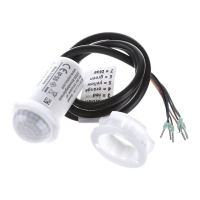
The wall base and the sensor can be plugged into one another. To install, disconnect both
parts. Insert a screwdriver into the side opening and lever off towards the sensor, pulling the
wall connection base away from the sensor (fig. 2.1). If mounting on a wall, the cable entry
points must face downwards. If mounting on ceiling, they must face the front. Insert the
cable and mount the wall base in the desired position (fig. 3). Connect the motion sensor as
directed in the circuit diagram (fig. 4).
CAUTION: The maximum inrush current must not be exceeded when connecting to capacitive loads
such as electronic ballasts or fluorescent lamps with parallel compensation.
(4.1) Standard operating mode
(4.2) Parallel switching of max. 8 devices
(4.3) If switching inductance (e.g. relays, contactors, series connection units) the use of a
quenching circuit (A) may be required
(4.4) Standard operating mode with the added option of constant lighting mode using an
external switch
(4.5) Parallel switching and stairway lighting machine
(4.6) Standard operating mode with the added option of manual switching.
If fitting to a ceiling, the two sensor parts are turned away from each other by 180° (fig. 5).
Fit the detector onto the wall base and press to slot into position (fig. 2.2).
NB: The motion detector must always be fitted
so that the sensor faces down.
4 • STARTING UP AND SETTING
Once the device has been successfully installed and the power supply has been switched
back on, the device carries out an auto-test cycle lasting approx. 60 seconds. This is
indicated by the focus LED flashing and the connected loads being activated. Once this
phase is complete, the device is ready to use. The settings are concealed within the casing.
By pressing up and then letting go of the lens, the detector head is unlocked and protrudes
from the casing by approx. 1 cm. Repeat this procedure to allow the sensor head to return
to its original, locked position (fig. 6, works like a retractable ball-point pen). A range of
further setting options/special functions are available with the optional remote control Mobil-
RCi.
4.1 Test mode
Set the operating mode option button (fig. 7.1) to “Test”.
NB: Test mode can also be activated using the remote control Mobil RCi
(see section 6).
During test mode the focus LED is permanently switched on. Each time motion is detected,
regardless of the light exposure level, the detector switches the load ON for 1 second and
OFF for 2 seconds. The following options allow you to adjust the field of detection to suit the
environment in which the device is installed:
• Turning the sensor head horizontally by +/- 90° (unlock sensor head first, see fig. 6).
The central position is indicated by the red arrow.
• Control the range for each sensor field by mechanically raising each individual sensor.
(fig. 7.2). The position is displayed optically by the focus LED (fig. 8). The RC 130i has
1 sensor, the RC 230i has 2 and the RC 280i has 3.
• Use of the supplied covering cap for masking specific areas (fig. 9).
Once the field of detection is set, turn the operating switch to “ ”, to make the
adjustments using the settings on the device, or to “ ”, to run the default
programme or to make other settings using the remote control.
5 • OPERATING/PROGRAMMING
Every time movement is detected the focus LED lights up for 2 seconds. This function can be
switched off (see section 6). The motion detector switches the load on for the set length of
time, depending on the set light exposure level.
Setting unit operating mode button (fig. 7.1).
NB: The operating mode button allows you to set the parameters for the device. You can either
simply select the values using the settings (fig.s 7.3 and 7.4) on the device or use the default
programme, or the set parameters using the remote control. You can switch the settings at any
time; the defined values apply.
Test mode: See section Test Mode
Manual mode : Device operates according to the parameters on the settings
(fig. 7.3 and 7.4).
Auto/RC Modus : Devices operates according to the default programme or
the parameters defined using the remote control.
Default programme
Set the operating button (fig. 7.1) to “ ”. If no values have yet been defined with
the remote control, the detector operates according to the default programme. This consists
of two fixed values for the length of time the device is switched on, the electronic setting for
the field of detection and the light exposure level (2 minutes/maximum electronic range/
10 lux). These values can be individually adjusted using the remote control. To return
settings to the original default values, press the button (ensure that you are in
programming mode) on the remote control Mobil-RCi.
Activation time setting button (fig. 7.3)
Activation time adjustable: impulse, 15 seconds – 16 minutes. Impulse means that the device
is activated for approx. 1 second followed by a break of approx. 9 seconds in which no
movement is detected. The focus LED is activated for 2 seconds for each sequence. After the
break time a new sequence is triggered if motion is detected. This is suitable, for example,
to activate a gong.
Light exposure level setting button (fig. 7.4)
The light exposure level is infinitely variable between 2 – 2500 Lux.
Range control setting button (fig. 7.2)
Depending on the model there are 1 to 3 setting buttons. The control unit for setting the
range depends on the settings on the operating mode button.
Range control: from approx. 20 m – approx. 5 m.
• •
RC 130i
• •
RC 230i
• •
RC 280i
MOTION DETECTORS
www.esylux.com
MOTION DETECTORS
GB
FIG. 1
FIG. 2 FIG. 3 FIG. 4
FIG. 5 FIG. 6 FIG. 7
FIG. 8 FIG. 9 FIG. 10
7.1
4.1 4.2 4.3
4.4 4.5 4.6
2.1
2.2
7.2 7.3 7.4
6 • REMOTE CONTROL
NB: To use the remote control Mobil-RCi, the operating mode button must be set to
“ ” (fig. 7.1). If the operating button is set to “ ” and if no
parameters have yet been entered via the remote control, the device operates using a preset
default programme (10 Lux/2 minutes/max. electronic range).
All entries made by remote control are saved permanently. If there is a power cut, the
settings are restored. The settings can conveniently be made from the ground without the
need for a ladder or tools using the Mobil-RCi or Mobil- RCi-M (fig. 10) remote control.
For best results, point the remote control at the motion detector when programming the
device. Please note that if exposed to direct sunlight, the standard range of approx. 6 m
is considerably reduced on account of the infrared emissions from the sun.
6.1 Confirmation of commands on the device:
Command understood and carried out.
Focus-LED 2 seconds ON, the relay switches on twice for 1 second.
Command not understood.
Focus-LED flashes twice, the relay is not responding.
6.2 Standard functions/programming mode
There are basically two difference options for entering values via the remote control.
Standard functions
These functions can be selected directly:
• Test mode
• Continuous light mode ON/OFF
• Reading the current light exposure level
• Reset (reset the current modes)
• Master X
• Programming mode
Programming mode
These functions can only be selected/set if the device
is in programming mode button .
• Predefined light levels
• Predefined activation time
• Activating the impulse mode
• Holiday mode
• Alarm mode
• Creep zone protection ON/OFF
• Focus-LED ON/OFF
• Electronic range control
• Reset – (reset to default programme/factory settings)
NB: The special features impulse, vacation and alarm mode cannot be used at the same time.
The programme activated most recently is active.