ETC Installation Guide
SC1008 BCELTS
SC1008 BCELTS Page 2 of 11 ETC
Installation Requirements
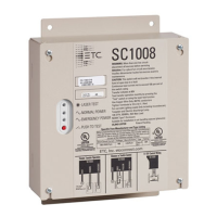
Install the SC1008 in a location that is accessible by qualified personnel for testing of the transfer
function using either a laser pointer (or similar) or the onboard test switch.
The SC1008 installs to a flat surface, has four conduit entry locations, and includes a universal
mounting plate with four mounting holes. Mounting and conduit hardware are provided by others.
Note:
Suitable for use in other spaces used for environmental air (plenums) in accordance
with Article 300 of the National Electrical Code (NFPA 70).
Ambient Environment
NEMA Type 1 Enclosure suitable for installation location that conforms to the following ambient
environment:
0°C–40°C, 5–95% non–condensing humidity
Electrical Specification
Note:
Continuous load current not to exceed 100% of the switch rating.
Use copper wire only, minimum 75°C conductors.
Normal and Emergency Rated Operational Voltage Input
120–277 VAC +/- 10%, 50/60 Hz
Load Rating
Supports a continuous load of up to 20A for tungsten and resistive load types, and supports
electronic ballast loads of up to 16A (80% of the switch rating)
Continuous load current not to exceed 100% of the switch rating
Transfer Initiation
When normal power is lost, meaning the voltage drops below 85 VRMS, the unit transfers the
output load to the emergency power source.
When normal power is restored, meaning the voltage rises above 90 VRMS, the unit transfers
the output load to the normal power source.
Short Circuit Current Rating
Short circuit capacity of 10kA
 Loading...