ETC Installation Guide
SC1008 BCELTS
SC1008 BCELTS Page 8 of 11 ETC
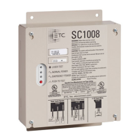
0–10V Auxiliary Output
The SC1008 features a single pole auxiliary relay that provides switching for installations utilizing 0–10V
or Digital Addressable Lighting Interface (DALI) controls. In the event of an emergency, the relay
opens the control circuit, sending any connected loads to their full intensity output.
+ (purple wire)
+ (purple wire)
- (grey wire)
0–10 V controller
0–10 V ballast
9
10
0–10 V
Note:
All low–voltage Class 2 wiring must be separated from all Class 1 wiring. Follow
local codes and installation restrictions.
ETC recommends limiting the distance run for the 0
–
10V control wiring from the controller
to the last ballast (driver) to 300ft (90m), based on 18AWG wire.
1. Run a +10V wire, typically purple, between the 0–10V controller and the 0–10V terminal 10
in the SC1008 and secure the terminal onto the wire.
2. Run a +10V wire, typically purple, between 0–10V ballast and the 0–10V terminal 9 in the
SC1008 and secure the terminal onto the wire.
3. Run a common wire, typically grey, between the 0–10V controller and the 0–10V ballast.
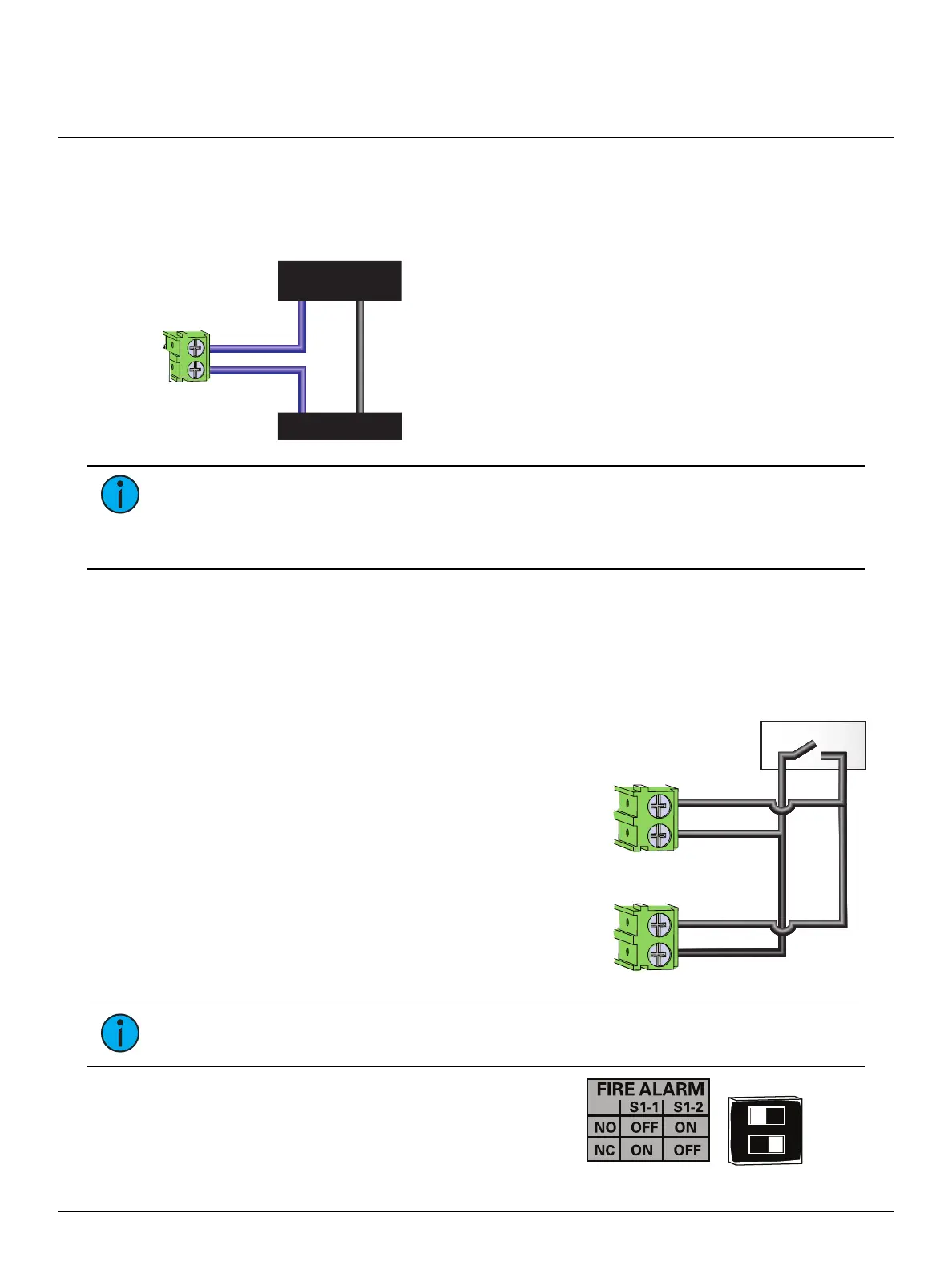
Fire Alarm Input
SC1008
SC1008
Connect up to
10 units
Fire Alarm
11
12
FIRE
ALARM
+
-
11
12
FIRE
ALARM
+
-
The SC1008 features a single dry contact input that can
be used to force the transfer from normal to emergency
state, even if both normal and emergency power are
present. The contact may be configured for either
normally closed (NC) or normally open (NO) operation by
setting switch 1 and 2 on the SC1008 control board.
1. Run a positive control wire between the fire alarm
device and the FIRE ALARM 11 “+” terminal in the
SC1008 and secure the terminal onto the wire.
2. Run a negative (common) control wire between
the fire alarm device and the FIRE ALARM terminal
12 “-”and secure the terminal onto the wire.
Note:
The system supports connection of up to ten SC1008 units connected in parallel to
the fire alarm device.
3. Set the fire alarm contact input configuration
switches for either normally open or normally closed
operation.
 Loading...