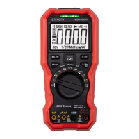
The Etekcity MSR-A600 Digital Multimeter is a versatile tool designed for various electrical measurements, ensuring accuracy and safety for both professional and home use. It complies with IEC61010 standards, featuring pollution degree 2, overvoltage category (CAT. II 600V), and double insulation, making it safe for use in diverse environments.
Function Description:
This multimeter is capable of measuring AC and DC voltage, resistance, continuity, diode, capacitance, and AC and DC current (microAmps, milliAmps, and Amps). Its rotary switch allows for easy selection between these functions. The device features an auto-range mode, which automatically selects the best resolution for measurements, and an auto power-off function to conserve battery life. A data hold feature allows users to freeze the displayed measurement on the LCD screen for convenient reading. The backlight function, which can be turned on or off by pressing and holding the HOLD/BACKLIGHT button for 2 seconds, is particularly useful in poorly lit areas, though it automatically turns off after 30 seconds.
Important Technical Specifications:
- Maximum Voltage: 600V
- Maximum Overload Protection: 600V rms (AC or DC)
- Measurement Speed: 2-3 times/second
- Fused Protection:
- VΩmAµA Terminal: 200mA
- 10A Terminal: 10A
- Temperature Range:
- Operating: 32° - 104°F (0°C - 40°C)
- Storage: 14° - 122°F (-10° - 50°C)
- Relative Humidity:
- ≤75% @ 0°~30°C
- ≤50% @ 30-40°C
- Maximum Display Value: 1999
- Overload Display: OL
- Battery Type: 2 x 1.5V AAA Batteries (Pre-installed)
- Dimensions: 5.5 x 3 x 1.9 in. (140 x 77 x 48 mm)
- Weight: 7.1 oz (204 g)
- Input Impedance: Approximately 10MΩ for voltage measurements.
- AC Voltage Frequency Response: 40Hz ~ 400Hz (sine wave RMS, average response).
- AC Current Frequency Response: 40 to 400 Hz.
- Diode Test: Open circuit voltage 2.1V, test current approximately 1mA. Silicon PN junction voltage 0.5~0.8V.
- Continuity Test: Buzzer sounds if resistance is less than 10Ω. Reads "OL" if resistance is greater than 50Ω.
Accuracy Specifications (based on 64.4°-82.4°F / 18°-28°C):
- DC Voltage:
- 200.0mV: ± (0.7%+3)
- 2000mV: ± (0.5%+2)
- 20.00V, 200.0V, 600V: ± (0.7%+3)
- AC Voltage:
- 200.0mV: ± (1.0%+2)
- 2.000V: ± (0.7%+3)
- 20.00V, 200.0V, 600V: ± (1.0%+3)
- Resistance:
- 200.0Ω: ± (1.0%+2)
- 2000Ω, 20.00KΩ, 200.0KΩ: ± (0.8%+2)
- 20.00MΩ: ± (1.2%+5)
- 200.0MΩ: ± (5.0%+5)
- Capacitance (Under REL mode):
- 2.000nF, 20.00nF, 200.0nF: ± (4%+10)
- 2000μF, 20.00μF, 200.0μF: ± (3%+5)
- 2.000mF: ± (3%+10)
- DC Current:
- 200.0μA, 2000μA, 20.00mA, 200.0mA: ± (1.0%+2)
- 2.000A, 10.000A: ± (1.2%+5)
- AC Current:
- 200.0μA, 2000μA, 20.00mA, 200.0mA: ± (1.2%+3)
- 2.000A, 10.000A: ± (1.5%+5)
Usage Features:
- Safety First: Always connect the black test lead before the red, and disconnect the red before the black. Keep fingers behind finger guards on test probes. Never measure voltages exceeding 600V.
- Voltage Measurement: For AC or DC voltage, insert leads into COM and VΩmAµA terminals, select the appropriate rotary dial setting (V~ for AC, V--- for DC, mV≡ for mV), and connect to the object.
- Resistance Testing: Disconnect circuit power and discharge capacitors before measuring. Insert leads into COM and VΩmAµA terminals, select Ω, and connect to the object. "OL" indicates an open circuit or resistance beyond range.
- Continuity Testing: Disconnect circuit power and discharge capacitors. Insert leads into COM and VΩmAµA terminals, select the continuity setting, and connect to the object. A beep indicates continuity.
- Diode Testing: Disconnect circuit power and discharge capacitors. Insert leads into COM and VΩmAµA terminals, select the diode setting, and connect to the diode.
- Capacitance Testing: Always turn off power and safely discharge capacitors before testing. Insert leads into COM and VΩmAµA terminals, select the capacitance setting, and connect to the capacitor. The Relative Mode (SEL/REL button) can be used for low capacitance values.
- Current Measurement: Always ensure power is off and leads are connected in series. For microamps (μA) or milliamps (mA), use the VΩmAµA terminal. For Amps (A), use the 10A terminal. Select the correct current range with the rotary dial. Use SEL/REL for AC current. If unsure of the range, start with the highest (10A). Do not measure currents greater than 10A for more than 10 seconds.
Maintenance Features:
- Cleaning: Regularly dust the multimeter with a dry cloth. Do not use cleaning detergents or abrasive cleaners.
- Battery Replacement: Replace batteries when the low battery indicator appears on the LCD.
- Disconnect test leads and turn the multimeter OFF.
- Remove the protective case.
- Unscrew the battery compartment cover on the back.
- Replace old 1.5V AAA batteries with new ones, observing correct polarity.
- Secure the battery compartment and replace the protective case.
- Always dispose of old batteries according to local environmental waste regulations. Remove batteries for extended storage.
- Fuse Checking and Replacement:
- 10A Fuse: Check before each use. Plug the red test lead into VΩmAµA, turn the dial to continuity, and insert the red lead into the 10A terminal. A beep indicates the fuse is good. If no beep and "OL" is displayed, the fuse is overloaded and needs replacement.
- 200mA Fuse: If the display reads "0.0" when measuring current using the VΩmAµA terminal, the 200mA fuse needs replacement.
- Fuse Specifications: 10A Terminal Fuse: 10A/600V Φ5x20mm; VΩmAµA Terminal Fuse: 200mA/600V Φ5x20mm.
- Replacement Procedure:
- Disconnect test leads and turn the multimeter OFF.
- Remove the rubber case.
- Unscrew the bottom screws and carefully separate the front and rear panels.
- Replace the fuse(s) in the correct ports.
- Reconnect panels, secure screws, and replace the protective case.
- Only use specified fuses to avoid electrical shock or damage.
The Etekcity MSR-A600 Digital Multimeter is a reliable and user-friendly device, designed to provide accurate measurements while prioritizing user safety through clear instructions and robust protective features.