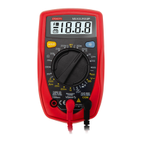
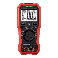
This document describes the Etekcity MSR-U1000 Digital Multimeter, a versatile auto-ranging multimeter designed for various electrical measurements.
Function Description
The MSR-U1000 Digital Multimeter is an advanced co-injection technique instrument that provides efficient insulation. It measures AC/DC Voltage, AC/DC Current, Resistance, Diode, Continuity, Buzzer, Capacitance, Frequency, hFE, and EF Function. It also includes additional features such as conventional measuring functions, data hold, relative mode, peak measurement, low battery display, display backlight, and sleep mode.
Important Technical Specifications
General Specifications:
- Maximum Voltage between any Terminals and Grounding: Refer to the different ranges input protection voltage.
- Fused Protection for µAmA Input Terminal: 1A H 240V Φ6x25mm.
- Fused Protection for 10A Input Terminal: 10A H 240V Φ6x25mm.
- Display: Maximum reading 4000 (frequency 9999), analogue bar graph 41 segments.
- Measurement Speed: Updates 2~3 times/second.
- Range: Auto or Manual.
- Polarity Display: Auto.
- Overload Indication: Display OL.
- Battery Deficiency: Display.
- Temperature:
- Operating: 0°C to +40°C (32°F to +104 °F).
- Storage: -10°C to +50°C (14 °F to +122 °F).
- Relative Humidity:
- ≤75% @ 0°C ~ 30°C below.
- ≤50% @ 30 - 40°C.
- Battery Type: One piece of 9V (NEDA1604 or 6F22 or 006P).
- Under the influence of radiated Radio-Frequency electromagnetic Field phenomenon: The captioned model has a measurement error, which will be back to normal when the interference is removed.
- Dimensions (HxWxL): 180 x 87 x 45mm / 7.1 x 3.4 x 1.8inch.
- Weight: Approximately 384g / 13.6oz (battery included).
- Safety/Compliances: IEC61010 CAT.III 1000V, CAT.IV 600V overvoltage and double insulation standard.
- Certifications: CE.
Accuracy Specifications (± a% reading + b digits, guarantee for 1 year, Operating temperature 18°C~28°C, Relative humidity <75%):
A. DC Voltage:
- 400mV: Resolution 0.1mV, Accuracy ±(0.8%+3), Input Impedance Around >3000MΩ, Fixed Value Input 1000V dc / 750V ac.
- 4V: Resolution 0.001V, Accuracy ±(0.5%+1), Input Impedance Around 10MΩ, Fixed Value Input 1000V dc / 750V ac.
- 40V: Resolution 0.01V, Accuracy ±(0.5%+1), Input Impedance Around 10MΩ, Fixed Value Input 1000V dc / 750V ac.
- 400V: Resolution 0.1V, Accuracy ±(0.5%+1), Input Impedance Around 10MΩ, Fixed Value Input 1000V dc / 750V ac.
- 1000V: Resolution 1V, Accuracy ±(1.0%+3), Input Impedance Around 10MΩ, Fixed Value Input 1000V dc / 750V ac.
B. AC Voltage:
- 4V: Resolution 0.001V, Accuracy ±(1.0%+3) (45Hz~400Hz), Input Impedance Around >3000MΩ, Fixed Value Input 1000V dc / 750V ac.
- 40V: Resolution 0.01V, Accuracy ±(1.0%+3) (45Hz~400Hz), Input Impedance Around 10MΩ, Fixed Value Input 1000V dc / 750V ac.
- 400V: Resolution 0.1V, Accuracy ±(1.0%+3) (45Hz~400Hz), Input Impedance Around 10MΩ, Fixed Value Input 1000V dc / 750V ac.
- 750V: Resolution 1V, Accuracy ±(1.2%+5) (45Hz~400Hz), Input Impedance Around 10MΩ, Fixed Value Input 1000V dc / 750V ac.
- Displays effective value of sine wave. mV range is applicable from 5% of range to 100% of range.
C. DC Current:
- 400µA: Resolution 0.1µA, Accuracy ±(1.0%+2), Overload Protection Fuse 1: F1A H 240V(CE), Φ6 x 25mm.
- 4000µA: Resolution 1µA, Accuracy ±(1.0%+2), Overload Protection Fuse 1: F1A H 240V(CE), Φ6 x 25mm.
- 40mA: Resolution 0.01mA, Accuracy ±(1.2%+3), Overload Protection Fuse 2: F10A H 240V (CE), Φ6 x 25mm.
- 400mA: Resolution 0.1mA, Accuracy ±(1.2%+3), Overload Protection Fuse 2: F10A H 240V (CE), Φ6 x 25mm.
- 4A: Resolution 0.001A, Accuracy ±(1.5%+3), Overload Protection Fuse 2: F10A H 240V (CE), Φ6 x 25mm.
- 10A: Resolution 0.01A, Accuracy ±(1.5%+3), Overload Protection Fuse 2: F10A H 240V (CE), Φ6 x 25mm.
- Remarks:
- When ≤5A: Continuous measurement is allowed.
- When >5A: Continuous measurement less than 10 seconds at an interval more than 15 minutes.
D. AC Current:
- 400µA: Resolution 0.1µA, Accuracy ±(1.2%+5) (45Hz~400Hz), Overload Protection Fuse 1: F1A H 240V (CE), Φ6 x 25mm.
- 4000µA: Resolution 1µA, Accuracy ±(1.2%+5) (45Hz~400Hz), Overload Protection Fuse 1: F1A H 240V (CE), Φ6 x 25mm.
- 40mA: Resolution 0.01mA, Accuracy ±(1.5%+5) (45Hz~400Hz), Overload Protection Fuse 2: F10A H 240V (CE), Φ6 x 25mm.
- 400mA: Resolution 0.1mA, Accuracy ±(1.5%+5) (45Hz~400Hz), Overload Protection Fuse 2: F10A H 240V (CE), Φ6 x 25mm.
- 4A: Resolution 0.001A, Accuracy ±(2.0%+5) (45Hz~400Hz), Overload Protection Fuse 2: F10A H 240V (CE), Φ6 x 25mm.
- 10A: Resolution 0.01A, Accuracy ±(2.0%+5) (45Hz~400Hz), Overload Protection Fuse 2: F10A H 240V (CE), Φ6 x 25mm.
- Remarks:
- When ≤5A: Continuous measurement is allowed.
- When >5A: Continuous measurement less than 10 seconds at an interval more than 15 minutes.
- Displays effective value of sine wave.
E. Resistance:
- 400Ω: Resolution 0.1Ω, Accuracy ±(1.2%+2), Overload Protection 1000V dc / 750V ac, Remark: When measuring below 2kΩ, apply REL Δ to ensure measurement accuracy.
- 4kΩ: Resolution 0.001kΩ, Accuracy ±(1.0%+2), Overload Protection 1000V dc / 750V ac, Remark: When measuring below 2kΩ, apply REL Δ to ensure measurement accuracy.
- 40kΩ: Resolution 0.01kΩ, Accuracy ±(1.0%+2), Overload Protection 1000V dc / 750V ac, Remark: When measuring below 2kΩ, apply REL Δ to ensure measurement accuracy.
- 400kΩ: Resolution 0.1kΩ, Accuracy ±(1.0%+2), Overload Protection 1000V dc / 750V ac, Remark: When measuring below 2kΩ, apply REL Δ to ensure measurement accuracy.
- 4MΩ: Resolution 0.001MΩ, Accuracy ±(1.2%+2), Overload Protection 1000V dc / 750V ac, Remark: When measuring below 2kΩ, apply REL Δ to ensure measurement accuracy.
- 40MΩ: Resolution 0.01MΩ, Accuracy ±(1.5%+2), Overload Protection 1000V dc / 750V ac, Remark: When measuring below 2kΩ, apply REL Δ to ensure measurement accuracy.
F. Capacitance:
- 40nF: Resolution 0.01nF, Accuracy ±(3.0%+5), Overload Protection 1000V dc / 750V ac, Remark: There is around 10nF residual reading when the circuit is open.
- 400nF: Resolution 0.1nF, Accuracy ±(3.0%+5), Overload Protection 1000V dc / 750V ac, Remark: There is around 10nF residual reading when the circuit is open.
- 4µF: Resolution 0.001µF, Accuracy ±(3.0%+5), Overload Protection 1000V dc / 750V ac, Remark: There is around 10nF residual reading when the circuit is open.
- 40µF: Resolution 0.01µF, Accuracy ±(3.0%+5), Overload Protection 1000V dc / 750V ac, Remark: There is around 10nF residual reading when the circuit is open.
- 400µF: Resolution 0.1µF, Accuracy ±(4.0%+5), Overload Protection 1000V dc / 750V ac, Remark: There is around 10nF residual reading when the circuit is open.
- 4000µF: Resolution 1µF, Accuracy unspecified, Overload Protection 1000V dc / 750V ac, Remark: There is around 10nF residual reading when the circuit is open.
G. Frequency Measurement:
- 10Hz~10MHz: Accuracy (0.1%+4), Maximum Resolution 0.01Hz.
- Overload Protection: 1000Vdc/750V ac.
- Input Amplitude: (DC electric level is zero)
- When 10Hz ~ 10MHz: 200mV ≤ a ≤ 30Vrms.
- When measuring on line frequency or duty cycle under AC Voltage and Current measurement mode, the input amplitude and frequency response must satisfy the following requirement: Input amplitude ≥range X 30%, Frequency response: ≤400Hz.
H. Diode Test:
- Resolution: 0.001V.
- Remarks: Open circuit voltage around 2.8V.
- Overload Protection: 1000Vdc / 750Vac.
I. Continuity Test:
- Resolution: 0.1Ω.
- Overload Protection: 1000Vdc / 750Vac.
- Remarks:
- Open circuit voltage is around 0.45V.
- Broken circuit resistance value is around >35Ω, the buzzer does not beep.
- Good circuit resistance value is ≤10Ω, the buzzer beeps continuously.
J. Transistor hFE (Model UT61A only):
- Range: hFE.
- Resolution: 1β.
- Remark: Ibo = 10µA, 1000 β MAX.
Usage Features
Rotary Switch:
The rotary switch allows selection of various measurement functions:
- VmV~: AC and DC Voltage Measurement.
- Ω: Resistance Measurement.
- Diode Test: For testing diodes.
- Continuity Test: For checking circuit continuity.
- Capacitance Test: For measuring capacitance.
- Hz %: Frequency and Duty Cycle Test.
- hFE: Transistor measurement.
- µA~, mA~: DC and AC current measurement.
- 10A~: 10A DC and AC current measurement.
- EF: Sensor Test.
- OFF: Power off.
Functional Buttons:
- HOLD Button:
- Press to enter/exit Hold mode.
- In Hold mode, "H" is displayed.
- Warning: Do not use Hold mode to determine if circuits are without power.
- LIGHT Button: Press and hold for 2 seconds to turn the display backlight on or off. Automatically turns off after about 25 seconds.
- BLUE Button: Press to select the alternate function when multiple functions are available at one rotary switch position.
- RANGE Button:
- Press to enter manual ranging mode.
- Press to step through available ranges.
- Press and hold for over 2 seconds to return to autoranging.
- MAX/MIN Button:
- Press to start recording maximum and minimum values.
- Steps the display through MAX and MIN readings.
- Enters manual ranging mode after pressing.
- Press and hold for over 2 seconds to exit MAX MIN mode.
- REL Δ Button (Relative Value Mode):
- Applies to all measurement functions except frequency/duty cycle.
- Subtracts a stored value from the present measurement value.
- Press to enter REL mode, locks the present range, and displays "0".
- Press again to reset the stored value and exit REL mode.
Measurement Operations:
- DC/AC Voltage Measurement:
- Insert the red test lead into the V terminal and the black test lead into the COM terminal.
- Set the rotary switch to V; DC measurement is default or press BLUE button to switch between DC and AC measurement mode.
- Connect the test leads across the object being measured.
- Display effective value of sine wave (mean value response).
- Input Amplitude: (DC electric level is zero), Input Amplitude: ≥range X 30%, Frequency response: ≤400Hz.
- DC/AC Current Measurement:
- Insert the red test lead into the mAµA or A input terminal and the black test lead into the COM terminal.
- Set the rotary switch to µA, mA, or A.
- The Meter defaults to DC current measurement mode. To toggle between DC and AC current measurement function, press BLUE button.
- Connect the test lead in serial to the return circuit to be tested.
- Display effective value of sine wave (mean value response).
- Press Hz% to obtain the frequency and duty cycle value.
- Input Amplitude: (DC electric level is zero), Input Amplitude: ≥range X 30%, Frequency response: ≤400Hz.
- Measuring Resistance:
- Insert the red test lead into the Ω terminal and the black test lead into the COM terminal.
- Set the rotary switch to Ω resistance measurement (Ω) is default or press BLUE button to select Ω measurement mode.
- Connect the test leads across with the object being measured.
- Testing for Continuity:
- Insert the red test lead into the Ω terminal and the black test lead into the COM terminal.
- Set the rotary switch to •))) and press BLUE button to select •))) measurement mode.
- The buzzer sounds continuously if the resistor to be tested is <10Ω. The buzzer does not sound if the resistor to be tested is >35Ω.
- Testing Diodes:
- Insert the red test lead into the Ω terminal and the black test lead into the COM terminal.
- Set the rotary switch to →+ and press BLUE button to select →+ measurement mode.
- For forward voltage drop readings on any semiconductor component, place the red test lead on the component's anode and place the black test lead on the component's cathode. The measured value shows on the display.
- Capacitance Measurement:
- Insert the red test lead into the →+ terminal and the black test lead into the COM terminal.
- Set the rotary switch to →+ and press BLUE button to select →+ measurement mode.
- At that time, the Meter will display a fixed value as below which is the Meter internal fixed distributed capacitance value (around 10nF). To ensure accuracy when measuring a small value of capacitance, the tested value must subtract this value. REL mode can help on that.
- For more convenience, use the included multi-purpose socket for measuring capacitor with leads or SMT capacitor. Insert the capacitor to be tested into the corresponding "+" and "-" jack of the multi-purpose socket. This method is more stable and correct for small value of capacitance testing.
- Connect the test leads across with the object being measured.
- Frequency Measurement:
- Insert the red test lead into the Hz terminal and the black test lead into the COM terminal.
- Set the rotary switch to Hz%; frequency measurement (Hz) is default or press Hz% button to select Hz measurement mode.
- Connect the test leads across with the object being measured.
- If you need to measure duty cycle, press Hz% button to select % measurement mode.
- Transistor hFE Measurement:
- Set the rotary switch to hFE.
- Insert the multi-purpose socket into the input terminal.
- Insert the transistor to be tested into the corresponding multi-purpose socket jacks.
- The LCD display hFE nearest value.
- EF Function (Non-Contact Voltage Detection):
- Set the rotary switch to EF and remove the test lead from the input terminals.
- Place the housing front part with marking towards the object being measured.
- When the test value is too high, the buzzer beeps and the red LED lights.
Maintenance Features
General Service:
- Periodically wipe the case with a damp cloth and mild detergent. Do not use abrasives or solvents.
- To clean the terminals with cotton bar with detergent, as dirt or moisture in the terminals can affect readings.
- Turn off the power of the Meter when it is not in use.
- Take out the battery when it is using for a long time.
- Do not use or store the Meter in a place of humidity, high temperature, explosive, inflammable and strong magnetic field.
- Warning: Do not attempt to repair or service your Meter unless you are qualified to do so and have the relevant calibration, performance test, and service information. To avoid electrical shock or damage to the Meter, do not get water inside the case.
Replacing the Battery:
- Turn the Meter power off and remove all connections from the terminals.
- Remove the screw from the tilt stand and the battery compartment and separate the battery compartment and the tilt stand from the case bottom.
- Remove the battery from the battery compartment.
- Replace the battery with a new 9V battery (NEDA1604, 6F22 or 006P).
- Rejoin the tilt stand, battery compartment and case bottom, and reinstall the screw.
- Warning: To avoid false readings, which could lead to possible electric shock or personal injury, replace the battery as soon as the battery indicator appears. Make sure the test leads are disconnected from the circuit being tested before opening the case bottom.
- Constantly check the battery as it may leak when it has been using for some time, replace the battery as soon as leaking appears. A leaking battery will damage the Meter.
Replacing the Fuses:
- Turn the Meter power off and remove all connections from the terminals.
- Remove the screw from the tilt stand and the battery compartment and separate the battery compartment and the tilt stand from the case bottom.
- Remove the two screws from the case bottom, and separate the case top from the case bottom.
- Remove the fuse by gently prying one end loose, then take out the fuse from its bracket.
- Install ONLY replacement fuses with the identical type and specification as follows and make sure the fuse is fixed firmly in the bracket.
- µA mA range: F1, 1A H 240V, Φ6x25mm. (CE)
- 10A range: F2, 10A H 240V, Φ6x25 mm. (CE)
- Rejoin the case bottom and case top, and reinstall the screw.
- Rejoin the tilt stand, battery compartment and case bottom, and reinstall the screw.
- Warning: To avoid electrical shock or arc blast, or personal injury or damage to the Meter, use specified fuses only in accordance with the following procedure.
- To test the fuse:
- Insert the red test lead into the Ω terminal and the black test lead into the COM terminal.
- Set the rotary switch to resistance measurement.
- Insert the test leads into the 10A and mAuA terminals and measure the resistance value between these two terminals. If the value is less than 0.5Ω, the fuses are OK; if the display appears OL, the fuses are broken.