6
STAND
The stand can be folded flat against the under side of the unit when not
in use or if the unit is to be operated in a horizontal position. It can be
swung down and forward until it hits the stops so that the unit can be
used in an inclined position. The stand was not designed to be a carrying
handle and should NOT be forced past the stops for this purpose.
DRY-WELL
The aluminium dry-well is located on the right hand side of the front
panel. Dry-well models have blocks with holes in to accept temperature
probes.
The 3001 dry-well is designed to accept four different probe sizes: two
Ø3.3, 4.0, 4.76 and 6.35 mm.
The 3002 dry-well is designed to accept four different probe sizes: Ø3.3,
4.76, 6.35 and 9.5 mm.
The 3003 dry-well is designed to accept two different probe sizes: 4.76
and 12.7 mm.
In addition to the Ø3.3 mm reference hole, the 3004 dry-well is designed
to accept a 13 mm removable brass insert for probe sizes Ø3.3, 4.1,
4.76, 6.4 and 9.5 mm and is supplied with an insert of the customer's
choice.
Use the nearest, larger size insert to the probe diameter being checked.
The inserts are a close fit in the dry-well to give good thermal conduction.
Keep the inserts clean and avoid damage by storing carefully. The
inserts MUST be regularly removed and cleaned to ensure they do not
seize in the dry-well. Do not introduce any liquids or substance into the
dry-well or inserts as this may result in the inserts sticking in the dry-well.
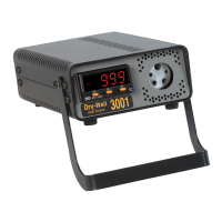
TEMPERATURE CONTROLLER
In normal operating mode the numeric LED display shows the actual
well temperature. A Control Output Indicator light (O1) is located in the
top left corner of the display. This indicates the on/off state of the heater
element in the block.
To show the set point temperature in the display press and release either
the up or down arrow button (
˄˅
). Press and hold either the up or down
arrow button (
˄˅
) to change the set-point value.
 Loading...