Safety Information and Maintanance
(Part of the Operating Instructions for Safety Switch CET/CTP (AS))
4
Subject to technical modications; no responsibility is accepted for the accuracy of this information. © EUCHNER GmbH + Co. KG 113769-03-11/15 (translation of the original operating instructions)
Inspection and service
WARNING
Loss of the safety function because of damage
to the system.
In case of damage, the affected module must be
replaced completely. Only accessories or spare
parts that can be ordered from EUCHNER may
be replaced.
Regular inspection of the following is necessary to
ensure trouble-free long-term operation:
Check the switching function
Check the secure fastening of the devices and
the connections
Check for soiling
Check the safe function of the safety guard par-
ticularly
after any setup work
after the replacement of a system component
after an extended period without use
after every fault
after any change to the DIP switch setting
No servicing is required; repairs to the device are
only allowed to be made by the manufacturer.
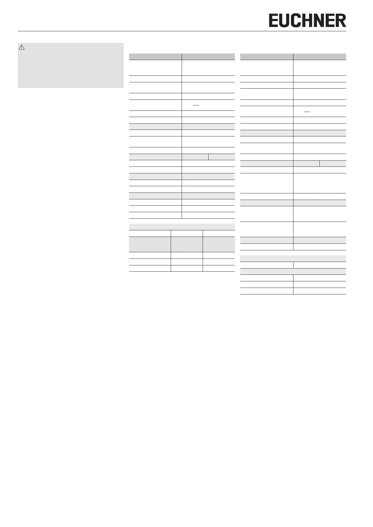
Technical data (extract)
Safety switch CET…
Parameter Value
Material
- Ramp
- Safety switch housing
Stainless steel
Die-cast aluminum
Mechanical life 1 x 10
6
operating cycles
Ambient temperature
at U
B
= DC 24 V
-20 .... +55 °C
Locking force F
max.
6,500 N
Locking force F
Zh
(incl. safety
margin acc. to GS-ET-19)
= 5,000 NF
Zh
=
F
max
1.3
Connection Plug connector M12, 4-pin
Risk time for single device 400 ms
Solenoid
Auxiliary voltage DC 24 V +10%/-15% (PELV)
Current consumption
with auxiliary voltage
400 mA
Duty cycle 100 %
AS-Interface data EA code: 7 ID code: B
Total current consumption Max. 30 mA
Valid AS-Interface addresses 1 - 31
AS-Interface inputs Acc. to ASi Safety at Work
Door monitoring contact D0, D1
Solenoid monitoring contact D2, D3
AS-Interface outputs
Guard locking solenoid D0, 1 = solenoid energized
Red LED D1, 1 = LED on
Green LED D2, 1 = LED on
Reliability values acc. to ENISO13849-1
Mission time 20 years 20 years
Monitoring of guard
locking and the safe-
ty guard position
Head downward
or horizontal
Head downward
Category 4 3
Performance Level (PL) e e
PFH
d
3.1 x 10
-9
/ h 4.29 x 10
-8
/ h
Safety switch CTP…
Parameter Value
Material
- Switch head
- Housing
Die-cast zinc
Fiber glass reinforced plastic
Installation position Any
Mechanical life 1 x 10
6
operating cycles
Ambient temperature
at U
B
= DC 24 V
-20 .... +55 °C
Locking force F
max.
1)
2,600 N
Locking force F
Zh
1)
according to ENISO14119
= 2,000 NF
Zh
=
F
max
1.3
Connection Plug connector M12, 4-pin
Risk time for single device 260 ms
Solenoid
Auxiliary voltage DC 24 V +10%/-15% (PELV)
Current consumption
with auxiliary voltage
400 mA
Duty cycle 100%
AS-Interface data EA code: 7 ID code: B
AS-i operating voltage 26.5 ... 31.6 V DC
Total current consumption
from AS-i
- CTP-..-AS.A
- CTP-..-AS.B
450 mA
50 mA
Valid AS-Interface addresses 1 - 31
AS-Interface inputs Acc. to ASi Safety at Work
Inuenced by door position
- CTP-..-AS1..
- CTP-..-AS2..
D0, D1
D0, D1, D2, D3
Inuenced by guard locking
- CTP-..-AS1..
- CTP-..-AS2..
D2, D3
D0, D1, D2, D3
AS-Interface outputs
Guard locking solenoid D0, 1 = solenoid energized
Reliability values acc. to ENISO13849-1
Mission time 20 years
Monitoring of guard locking and the safety guard position
Category 4
Performance Level (PL) e
PFH
d
4.3 x 10
-9
/h
1) Only applies in combination with straight actuators.

 Loading...


