Euphonix Max Air Control Surface Manual
7
System Startup Sequence
See page 21 in the Max Air Operation Manual for the system startup sequence.
Description
The Max Air Console consists of a configurable number of Control Modules that com-
prise the Control Surface. The Max Air Control Surface is the digital control center for
all Max Air system components and communicates with them via Ethernet network
connections. Control signals are transmitted via the Ethernet switch and distributed to
the Max Air system components. No audio passes through the Control Surface.
Overview
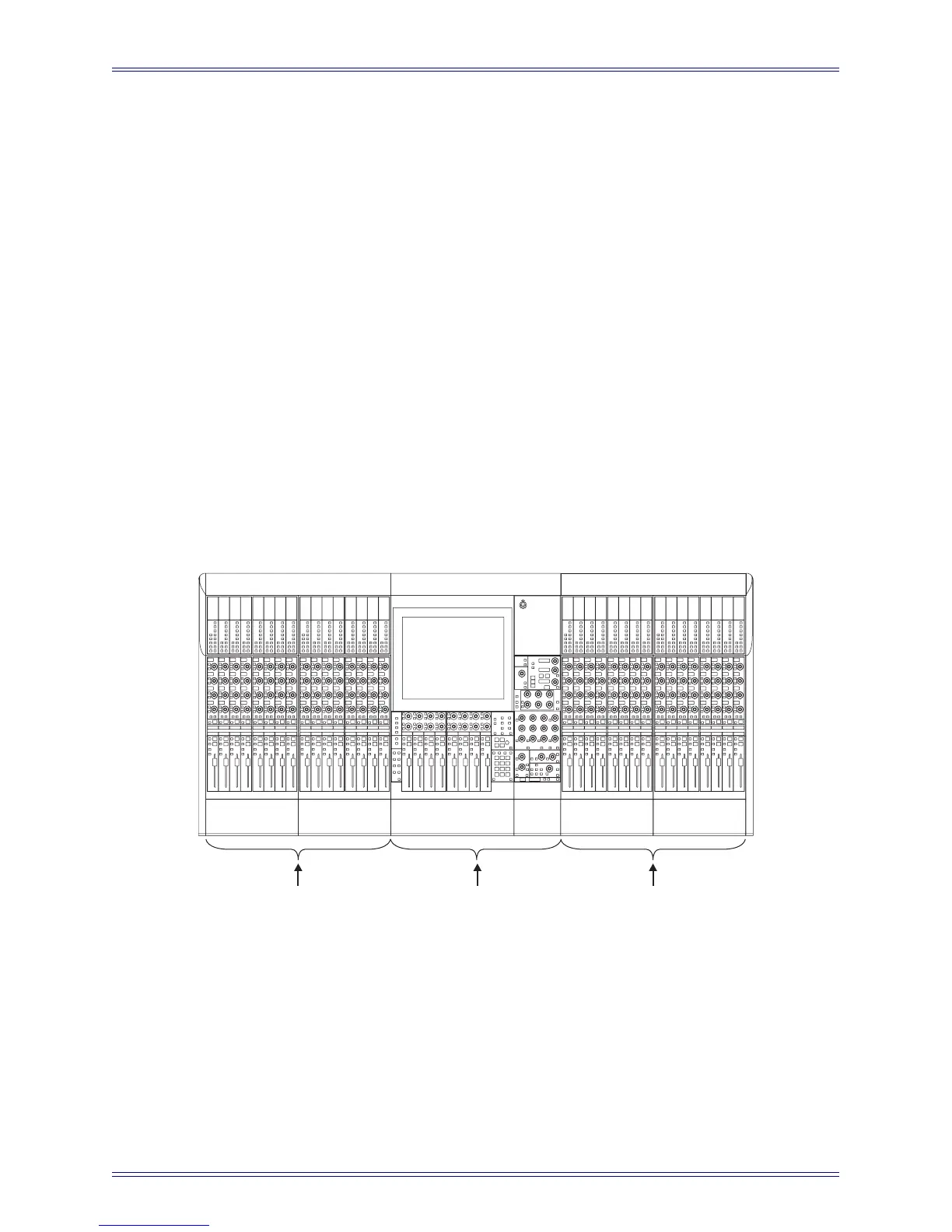
The Max Air console must contain a CM404 center section module and can have up to
three fully loaded CM416 16-channel Modules, each with 16 physical faders. The system
can have up to 48 faders, not including the eight faders in the CM404 master section.
The CM416HL and CM416HR are half-loaded (left or right) 8-fader modules that can
be used to expand your system.
Figure 1 Typical Console Layout
CM404
Center Section
CM416
Sixteen-channel Module
CM416
Sixteen-channel Module

 Loading...


