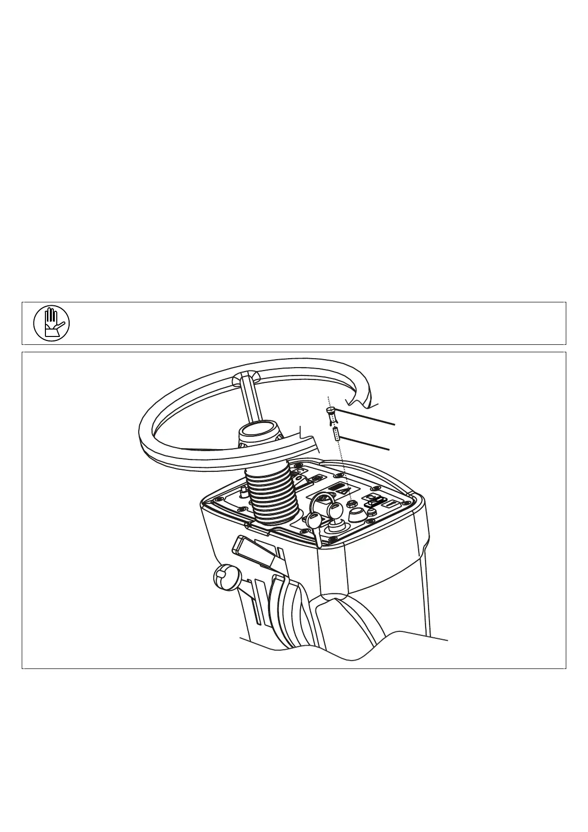
• Use a 3mm Allen key to remove the 10 fixing screws (pos. 3) of the control panel;
• Remove the control panel (pos. 6), lift it and attach it to the shaft of the wheel using the provided bracket (pos. 7),
ensuring not to jerk as this could damage the electrical system;
• From this position, the operator has access to all the components of the electrical system (remote switches, drive
control board, control panel components, fuses, etc.);
• Fuse holder (pos. 10): 50A DRIVE SYSTEM PROTECTION fuse;
TO REPLACE IT PROCEED AS FOLLOWS:
➢ Open the fuse holder cover (pos. 10);
➢ Unscrew the 2 nuts (pos. 12) that hold the fuse;
➢ Replace the 50A fuse (pos. 11) with a fuse of equal amperage and with the same characteristics;
➢ Put the nuts back into place and close the cover of the fuse holder.
• Fuse holder (pos. 9): 30A VACUUM MOTOR PROTECTION fuse;
To replace to carbon brushes, follow the instructions above;
• Put the control panel back inside the plastic end piece, ensuring not to jerk it as this could damage the electrical
system;
• Put the screws (pos. 3) back into place and tighten them using the provided key so as to given good pressure on the
gasket located beneath the panel.
After checking or replacing the fuses, put everything back into place and resume the operation.
To mount the hand-wheel, align the key on the shaft with the housing located on the hand-wheel and screw the nut (pos.
2).
One 5A glass fuse used to protect the control panel instruments is mounted in the control panel.
Follow the instructions below to check or replace the fuses:
• Unplug the battery connector;
• Do a ¼ turn left on the cover of the fuse holder (pos. 1) and remove it;
• The 5A glass fuse will also come out along with the cover;
• Check the fuse and if necessary replace it with one of equal amperage and with the same characteristics;
• Put the fuse and the cover in the fixed part of the fuse holder on the control panel, push and screw;
• Plug the battery connector back on.