5
h min= 15 cm
h max= 60 cm
Stilo 3 A=150 B=150
Stilo 4 A=200 B=200
B
B
B
A
B
D
90°
C
minimo
150 mm
Stilo 3 = max 150 mm
Stilo 4 = max 175 mm
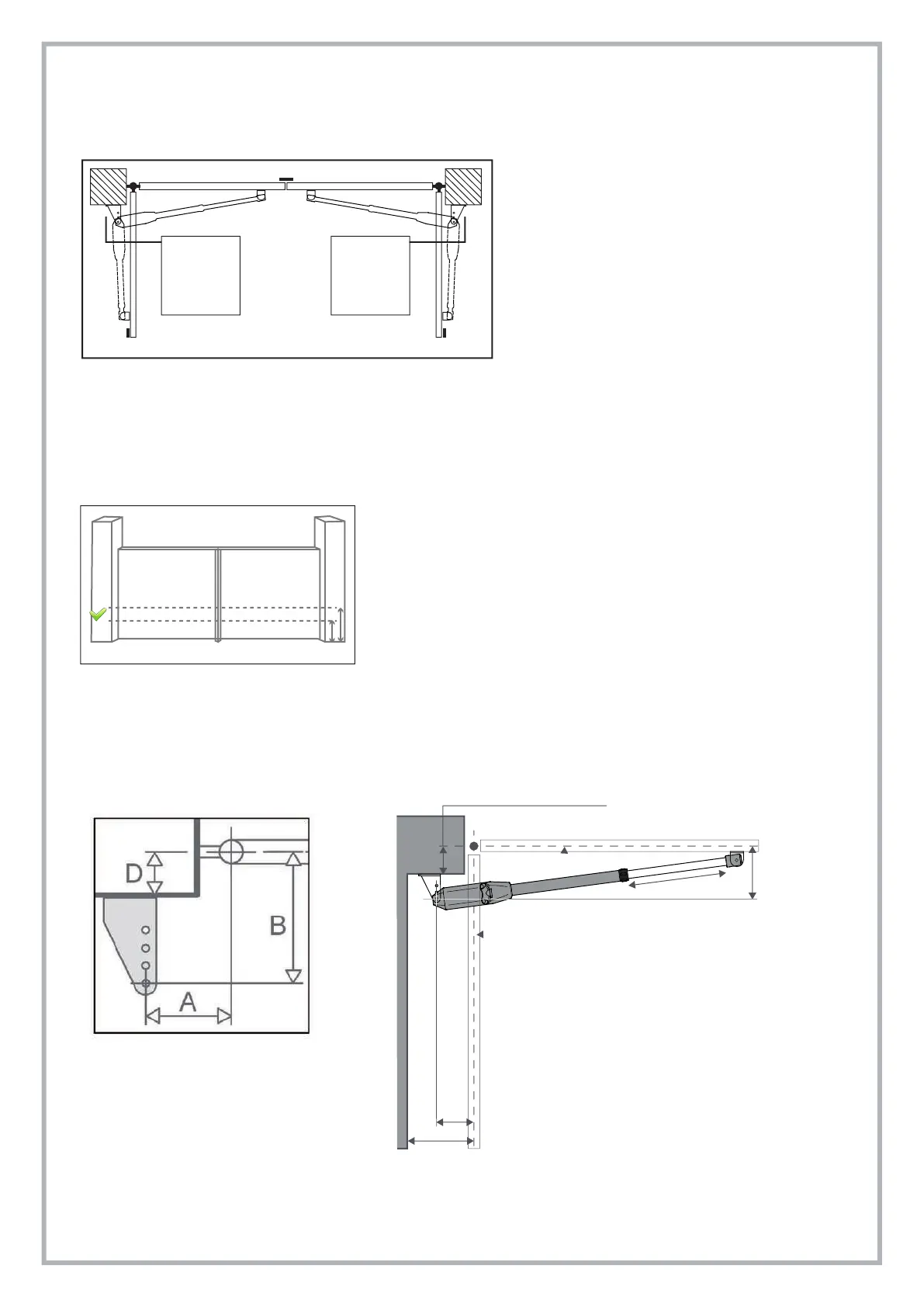
3.4 INSTALLING THE OPERATOR
The ram operators are supplied handless version, it means they can be installed either on the right or left side of the gate (see picture C).
Make sure that suitable ground stops (B) for opening and closing position of the leaves are in place.
B = mechanical ground stops
3.4.1. QUOTES FROM GROUND
The operator has to be fitted keeping a height from ground between 40 and 50 cm. See picture D.
If the gate is particularly light, fit the operator as closer as possible to gate centerline.
3.4.2. PILLAR BRACKETS – How to determine fixing dimensions
The ideal approach is to fix the brackets complying with the measures A and B as indicated in the below table
for an opening angle of 90° (picture E).
Pic. D
Pic. E
right
Motor
left
Motor
Pic. C
To determine the position of bracket S4:
Put the gate in closing position
Release the operator (see paragraph 4)
Move forward the front pivot of the operator until it reaches the position of limit switch in opening. Leave 20mm of space between the pivot
and the operator end (fig. O)
Fasten bracket S4 to the front pivot of the operator as indicated in pic. Q keeping in mind that the threaded hole of the rotating pivot must be
turned down and that the dragging pivot milling must be placed longitudinally to the hole (pic. P).
Put the operator on the gate’s wing keeping it levelled and mark the position of bracket S4 on the gate.
Weld or bolt bracket S4 to the gate.
Control that the drag pin has been positioned with the two sides of the milling in parallel position to the button hole of the alum. tube as
indicated in the pic. Q.