EasyManua.ls Logo

EUROSTER 2006 User Manual

EUROSTER 2006
15 pages
To Next Page IconTo Next Page
Page #1 background imageLoading...
Page #1 background image
EUROSTER 2006/2006TXRXG INSTALLATION AND OPERATION MANUAL 1
EUROSTER 2006/2006TX
Installation and operation manual
MANUFACTURER: P.H.P.U. AS, ul. Polanka 8a/3, 61-131 Poznań, Poland
Manual version: 28.09.2019
SPECIFICATION
EEPROM memory backup
for Heating or Cooling,by factory preset
temperature display range: 0 ~ 50°C
temperature control range: 5 ~ 35°C for Room mode, 5 ~ 45°C for Floor-heating
mode
temperature sampling rate: 1 minute
switching differential(Hysteresis): 0.2°C, 0.4°C or 1°C selectable to users
temperature sensing calibration: ± 2°C
temperature adjusting scale: 0.1°C (fast forward adjusting function, pressing + or
- for 3 seconds)
temperature display scale: 0.1°C
all 7-Day independently programmed
24-Hour- format, spread into 48 time adjusting zone
thermostat operate Power: 2 X AA 1.5 Vdc LR 6 Alkaline Battery-low indication
(when power goes below 2.4 Vdc)
thermostat output: 16(3.5) AMP / 250 Vac, Voltage-free, SPDT.
dimension: 138 L x 86 W x 29 H mm
CHOOSING INSTALLATION LOCATION
For obtaining thermostat's best performance upon using, recommend user to follow up
with precaution listed below.
1. Place thermostat on wall inside the room approximate 1.5 meter above floor.
2. Avoid position where temperature sensing easily interfered by ambience, such as,
directly exposed to Sun-Light, too near to any Heat-Generate devices
/refrigerator, right next to entrance/ exit/window, etc.
Question and Answer IconNeed help?

Do you have a question about the EUROSTER 2006 and is the answer not in the manual?

EUROSTER 2006 Specifications

General IconGeneral
BrandEUROSTER
Model2006
CategoryThermostat
LanguageEnglish

Summary

SPECIFICATION

CHOOSING INSTALLATION LOCATION

SAFETY RULES

OUTSIDE VIEW OF THE CONTROLLER

DISPLAY

TO OPEN TOP HOUSING

CHOOSING THERMOSTAT OPERATION MODE & TO REPLACE BATTERIES

WIRING GUIDE

Floor - Heating System

Wiring diagram for connecting the thermostat to a floor heating system.

Gas - Fired boiler

Wiring diagram for connecting the thermostat to a gas-fired boiler.

Heating / Cooling System

Wiring diagram for connecting the thermostat to a heating or cooling system.

TO ADJUST HYSTERESIS (SWITCHING-DIFFERENTIAL)

TO ADJUST TEMPERATURE CALIBRATION

TO ADJUST CLOCK

TO ADJUST AND TEMPERATURE SETTING

TO SET PROGRAM-PERIOD FOR EACH DAY AND START SETTING

SET UP THE SAME PROGRAMS FOR THE WHOLE WEEK

ACTORY PRESET PROGRAM-PERIOD

TO SET HOLD (PERMANENT OVERRIDE)

TO SET 5°C ANTI-FREEZE PROTECTION

TO SET MANUAL (TEMPORARY OVERRIDE)

RESTORING PRE-PROGRAMMED SETTINGS

SIMPLIFIED DECLARATION OF EU CONFORMITY

EUROSTER TXRXG WIRELESS VERSION

GENERAL DESCRIPTION

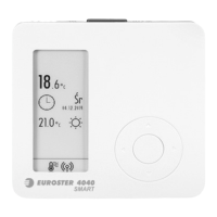
Provides an overview of the EUROSTER TXRXG wireless version thermostat.

OUTSIDE VIEW

Details the external components and layout of the EUROSTER TXRXG controller.

FIRST LAUNCH OF THE WIRELESS CONTROLLER EUROSTER TXRXG

Instructions for the initial setup and launch of the wireless EUROSTER TXRXG controller.

OPERATION MODE SWITCH

PROTECTION

OPERATION

WIRING DIAGRAM EXAMPLE EUROSTER TXRXG

With a 230 V AC powered device

Wiring example for connecting the EUROSTER TXRXG to a 230V AC powered device.
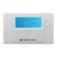
With a gas boiler

With a CH pump

TROUBLESHOOTING LIST

RECEIVER RX TECHNICAL DATA

MAINTENANCE

ELECTRONIC WASTE MANAGEMENT INFORMATION

WARRANTY CERTIFICATE

Related product manuals