2
PM SERIES FORCED DRAFT EVAPORATIVE CONDENSERS
The supporting I-beams should be level to within 1/8” in 6’ (1.5mm in 1m) before setting the unit. Do not level the unit by shimming
between the bottom flange and the beams as this will not provide proper longitudinal support.
NOTE: Consult the latest IBC code for required steel support layout and structural design.
Figure 1 – Structural Steel Support
A
B
Plan View
End Elevation
H
LIFTING
U-BOLTS
H
LIFTING
U-BOLTS
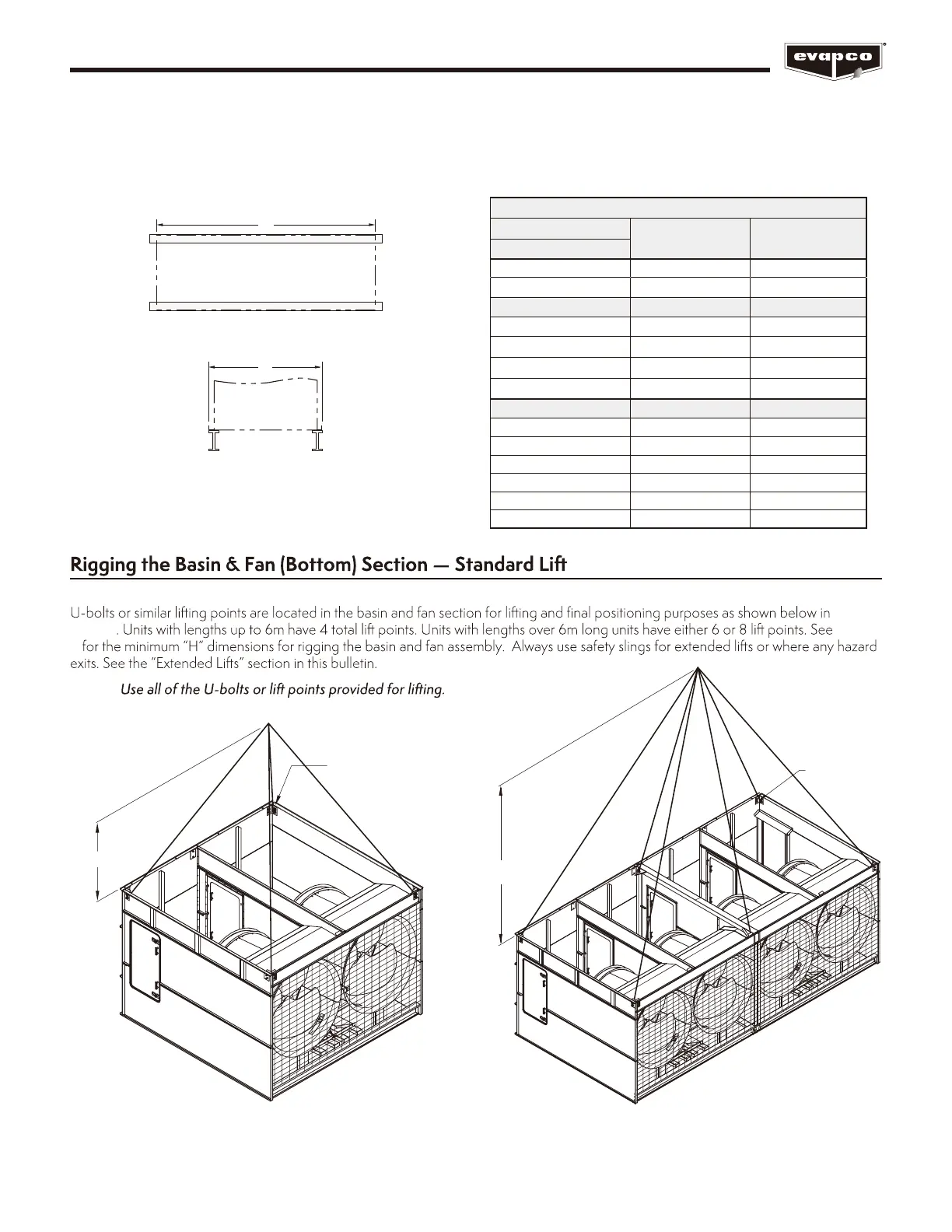
Figure 2 – Basin & Fan Section
(up to 6m Long)
Figure 3 – Basin & Fan Section
(over 6m Long)
Figures
2 and 3
Table
2
NOTE:
Table 1 – Steel Support Dimensions
(See Table 2 for model numbers corresponding to box size)
PMRC
Box Size
A (mm) B (mm)
1.9m Wide Models
6’ x 12’ (1.9m x 3.6m) 3648 1930
6’ x 18’ (1.9m x 5.5m) 5490 1930
3m Wide Models A (mm) B (mm)
10’ x 12’ (3m x 3.6m) 3651 2991
10’ x 18’ (3m x 5.5m) 5490 2991
10’ x 24’ (3m x 7.3m) 7337 2991
10’ x 36’ (3m x 11m) 11024 2991
3.6m Wide Models A (mm) B (mm)
12’ x 12’ (3.6m x 3.6m) 3651 3616
12’ x 18’ (3.6m x 5.5m) 5490 3616
12’ x 20’ (3.6m x 6m) 6102 3616
12’ x 24’ (3.6m x 7.3m) 7337 3616
12’ x 36’ (3.6m x 11m) 11024 3616
12’ x 40’ (3.6m x 12.2m) 12243 3616