3
PM SERIES FORCED DRAFT EVAPORATIVE CONDENSERS
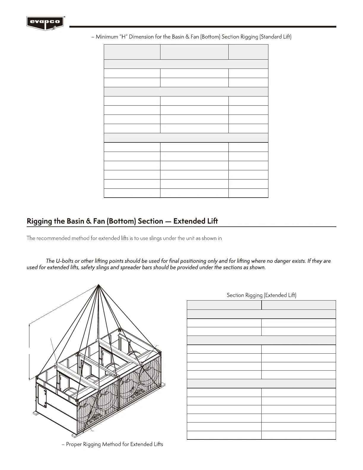
Figure 4. Spreader bars should always be used
between the cables at the top of the section to prevent damage to the upper flanges. See Table 3 for the minimum “H” dimensions for
rigging the basin and fan assembly.
NOTE:
Safety slings, spreaders, and skids should be removed before final positioning of the unit.
H
SAFETY
SLING
76mm x 200mm
SPREADERS
SAFETY SLING
Figure 4
Table 2
Table 3 – Minimum “H” Dimension for the Basin & Fan (Bottom)
(See Table 2 for model numbers corresponding to box size)
*This box size has two 12’ (3.6m) long heat transfer casing top sections.
Box Size Model Numbers
“H”
Dimension (m)
1.9m Wide Models
6’ x 12’ (1.9m x 3.6m)
PMC-175E to 240E
3.6
6’ x 18’ (1.9m x 5.5m)
PMC-250E to 375E
5.2
3m Wide Models
10’x12’ (3m x 3.6m) PMRC-332 to PMRC-530 4.3
10’x18’ (3m x 5.5m) PMRC-503 to PMRC-792 5.5
10’x24’ (3m x 7.3m) PMRC-725 to PMRC-1056 7
10’x36’ (3m x 11m) PMRC-1006 to PMRC-1586 10
3.6m Wide Models
12’ x 12’ (3.6m x 3.6m) PMRC-376 to PMRC-678 4.6
12’ x 18’ (3.6m x 5.5m) PMRC-568 to PMRC-1012 5.8
12’ x 20’ (3.6m x 6m) PMRC-715 to PMRC-1074 6
12’ x 24’ (3.6m x 7.3m)* PMRC-816 to PMRC-1362 7
12’ x 36’ (3.6m x 11m) PMRC-1137 to PMRC-2024 10
12’ x 40’ (3.6m x 12.2m) PMRC-1705 to PMRC-2138 11
Box Size “H” Dimension (m)
1.9m Wide Models
6’ x 12’ (1.9m x 3.6m) 3.6
6’ x 18’ (1.9m x 5.5m) 5.2
3m Wide Models
10’ x 12’ (3m x 3.6m) 4.3
10’ x 18’ (3m x 5.5m) 5.5
10’ x 24’ (3m x 7.3m) 7
10’ x 36’ (3m x 11m) 10
3.6m Wide Models
12’ x 12’ (3.6m x 3.6m) 4.6
12’ x 18’ (3.6m x 5.5m) 5.8
12’ x 20’ (3.6m x 6m) 6
12’ x 24’ (3.6m x 7.3m) 7
12’ x 36’ (3.6m x 11m) 10
12’ x 40’ (3.6m x 12.2m) 11
 Loading...