6
PM SERIES FORCED DRAFT EVAPORATIVE CONDENSERS
Assembly of the Heat Transfer Casing (Top) Section to the Basin & Fan (Bottom) Section
Before assembling the heat transfer casing (top) section to the cold water basin and fan (bottom) section, remove any loose parts shipped
in the basin.
Wipe the flanges on the bottom of the casing section. Check to see that the water distribution connection on the casing section is in the
correct position relative to the basin and fan section (see certified print). Units are also provided with match markings on each section, as
shown in Appendix A. Confirm that sealer tape has been applied to the top of the basin and fan section as shown in Figures 5 and 6.
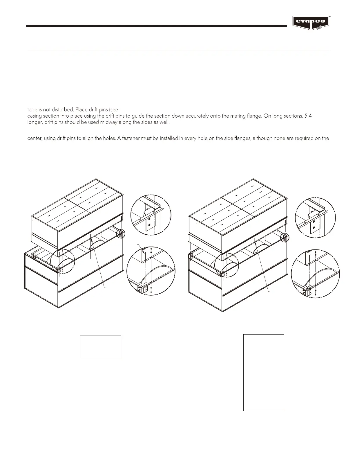
Lower the casing section to within several inches of the basin and fan section, making sure the two sections do not touch and the sealer
Figure 12 and 13) in at least three (3) of the corner mounting holes and gradually lower the
m and
Place fasteners in all four (4) corner bolt holes. Then, continue to install the rest of the fasteners working from the corners toward the
end flanges.
For units with two casing sections, mount the first as described, and then follow the same procedure for the second section.
A
DETAIL A
B
DETAIL B
USE FOR
5.4m AND
LARGER
DRIFT
PIN
Figure 12 – Mating Casing (Top) Section to
Basin & Fan (Bottom) Section
BOX SIZES:
1.9m x 3.6m
1.9m x 5.5m
A
DETAIL A
B
DETAIL B
USE FOR
5.4m AND
LARGER
Figure 13 – Mating Casing (Top) Section to
Basin & Fan (Bottom) Section
BOX SIZES:
3m x 3.6m
3m x 5.5m
3m x 7.3m
3m x 11m
3.6m x 3.6m
3.6m x 5.5m
3.6m x 6m
3.6m x 7.3m
3.6m x 11m
3.6m x 12.2m