EasyManua.ls Logo

Evco EVF214 - User Manual

Evco EVF214
8 pages
Print Icon
To Next Page IconTo Next Page
Loading...
Evco S.p.A. • Code 104F214E00 • page 1/8
EVF214 Digital controller for refrigerated cabinets, made up from user interface with capacitive touch keys
(integrated into the unit) and a control module version 1.00
EN
ENGLISH
1 IMPORTANT
1.1 Important
Read these instructions carefully before installation and before use and follow all installation recommendations regarding installation and the electric connections. Keep the instructions with the instrument for future
consultation.
The instrument must be disposed of in compliance with the local Standards regarding the collection of electrical and electronic appliances.
2 INTRODUCTION
2.1 Introduction
EVF214 is a digital controller developed for the management of normal
or low temperature refrigerated cabinets. whose design and easy
cleaning cover an important role.
The instrument has:
clock
alarm buzzer
3 measurement inputs (cabinet probe, evaporator probe and
condenser probe) for NTC probes
2 digital inputs (door micro switch and multipurpose)
4 digital outputs (relays) for compressor management
(30 A @ 250 VAC), defrost and evaporator fan management and a
fourth utility (cabinet light, demisting heater, auxiliary output, alarm
output, door heater, evaporator valve or condenser fan).Defrosting
can be electric or using hot gas.
TTL serial port with MODBUS communication protocol.
The models have “split” execution (user interface + control module).
The user interface is behind a methacrylate sheet and is made up from
a 4-digit custom display (with icon function) and 6 capacitive touch
keys (set, up, down, defrosting, cabinet light and on/stand-by); back
panel installation is envisioned, using double-sided adhesive tape, for
its complete mechanical and aesthetic integration into the cabinet.
The control module is in open frame board; installation is envisioned
on a flat surface with spacers.
Using the EVKEY programming key (to be ordered separately)
configuration parameters can be uploaded and downloaded.
Using a serial interface (to be ordered separately) it is also possible to
connect the controller to the Parameters Manager set-up software or
to the monitoring and supervision system of RICS plants (via TTL, with
MODBUS communication protocol).
3 DIMENSIONS AND INSTALLATION
3.1 User interface dimensions
The dimensions are expressed in mm (in); installation is envisioned behind the panel using double-sided adhesive tape.
3.2 Control module dimensions
The dimensions are expressed in mm (in); installation is envisioned on a flat surface using spacers.
3.3 Recommendations for installation
make sure that the work conditions (temperature of use, humidity,
etc.) lie within the limits indicated in the technical data
do not install the instrument in proximity of heat sources (heaters,
hot air pipes etc.) appliances with strong magnets (large diffusers
etc.), places subject to direct sunlight, rain, humidity, excessive dust,
mechanical vibrations or shocks
any metal parts in proximity of the control module must be at a
distance such as not to compromise the safety distances
in compliance with Safety Standards, the protection against any
contact with the electric parts must be ensured via correct installation
of the instrument. All parts that ensure protection must be fixed in a
way such that they cannot be removed without the aid of a tool.
4 USER INTERFACE
4.1 Preliminary considerations
The following functioning states exist:
the “on” status (the instrument is powered and on: the regulators can
be on)
the “stand-by” status (the instrument is powered but is switched off
software: the regulators are off, the possibility of switching the cabinet
light or auxiliary output on/off in manual mode depends on parameter
u2)
the “off” status (the instrument is not powered).
Successively, the term “switch-on” means that the passage from the
stand-by status to the on status; the term “switch-off” means the passage
from the on status to the stand-by status.
When the instrument is powered it re-proposes the status in which it
found itself at the time when the power supply was disconnected.
4.2 Instrument switch-on/off in manual mode
make sure that the keyboard is not locked and that no procedure is
in progress
hold the
key down for 2 s: the on/stand-by LED switches-on/off.
The multipurpose input can also be used to switch the instrument on/
off in remote mode.
4.3 The display
If the instrument is on, during normal functioning the display will
show the temperature of the cabinet, except during defrosting, when
the instrument will display the temperature established with
parameter d6.
If the instrument is off, the display will be off.
4.4 Evaporator temperature display
make sure that the keyboard is not locked and that no procedure is
in progress
hold the
key down for 1 s: the display will show the first label
available
press and release the
key or the key to select “Pb2
press and release the
key.
To exit the procedure:
press and release the
key or do not operate for 60 s
press and release the
key or the key until the display shows the
cabinet temperature or do not operate for 60 s.
Alternatively:
press and release the
key.
If the evaporator probe is absent (parameter P3 = 0), the “Pb2” label
will not be displayed.
4.5 Condenser temperature display
make sure that the keyboard is not locked and that no procedure is
in progress
hold the
key down for 1 s: the display will show the first label
available
press and release the
key or the key to select “Pb3
press and release the
key.
To exit the procedure:
press and release the
key or do not operate for 60 s
press and release the
key or the key until the display shows the
cabinet temperature or do not operate for 60 s.
Alternatively:
press and release the
key.
If the condenser probe is absent (parameter P4 = 0), the “Pb3” label
will not be displayed.
4.6 Activation/deactivation of the Overcooling
function
make sure that the keyboard is not locked, that no procedure is in
progress and defrosting is not in progress along with dripping or
evaporator fan standstill.
hold the
key down for 4 s: the Overcooling LED will switch-on.
During the Overcooling function, the work set-point is decreased
from the temperature established by parameter r5; the function will
last for the time established by parameter r6.
Defrosting is never activated during the Overcooling function; if the
defrosting interval expires when the function is in progress, defrosting
will be activated on conclusion of the function.
4.7 Activation of defrosting in manual mode
make sure that the keyboard is not locked, that no procedure is in
progress and the Overcooling function is not in progress
hold the
key down for 4 s.
If the function of the evaporator probe is that of defrosting probe
(parameter P3 = 1) and on activation of defrosting the temperature of
the evaporator is above that established with parameter d2, defrosting
will not be activated.
Question and Answer IconNeed help?

Do you have a question about the Evco EVF214 and is the answer not in the manual?

Summary

Introduction to EVF214 Digital Controller

Product Overview

General description of the EVF214 digital controller for refrigerated cabinets.

Dimensions and Installation Guide

User Interface Dimensions

Physical size specifications for the user interface unit.

Control Module Dimensions

Physical size specifications for the control module unit.

Installation Recommendations

Guidelines for proper instrument placement and mounting.

User Interface Operation and Features

Basic Operation and States

Instrument power states, display, manual on/off, and output control.

Temperature Display and Special Functions

Viewing temperatures, Overcooling, Energy Saving, and Humidity control.

Manual Control Features

Manual defrosting, demisting heaters, keyboard lock, and buzzer silencing.

Instrument Settings and Configuration

Time, Set-point, and Parameter Setup

Configuring clock, target temperature, and operational parameters.

Factory Reset and Parameter Reference

Resetting to defaults and accessing parameter tables for reference.

HACCP Monitoring and Operational Tracking

HACCP Alarm Logging and Display

Storing and viewing HACCP alarm data and system indicators.

Compressor Hour Tracking and Indicators

Monitoring compressor hours and understanding signals/indications.

Alarm and Error Management

Alarm Conditions and Solutions

Details various alarm types and provides remedies for each.

System Errors and Troubleshooting

Error Codes and Troubleshooting

Explanation of system error codes and how to resolve them.

Technical Specifications

Technical Data Overview

Summary of the instrument's technical specifications and operating limits.

Parameter Reference Guide

Work Set-point Parameters

Detailed list and description of work set-point parameters.

Configuration Parameters: Inputs & Protections

Details on measurement inputs and compressor protection parameters.

Parameter Reference Guide (Continued)

Configuration Parameters: Defrosting, Alarms, Fans

Details on defrosting, temperature alarms, and evaporator fan settings.

Configuration Parameters: Digital I;O, Special Functions, Network

Details on digital I/O, energy saving, real-time functions, and Modbus.

Electrical Connections

Connection Preliminaries

Important notes and considerations before making electrical connections.

Wiring Diagram and Details

Visual guide and specific details for electrical hookup.

Installation Recommendations

Advice for safe and correct electrical installation procedures.

Overview

The EVF214 is a digital controller designed for managing refrigerated cabinets, suitable for both normal and low-temperature applications. Its design emphasizes ease of cleaning and integration within the cabinet.

Function Description

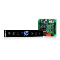
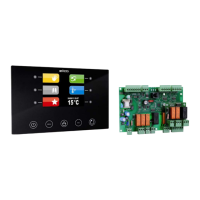
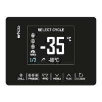
The controller operates in a "split" configuration, comprising a user interface and a control module. The user interface, integrated behind a methacrylate sheet, features a 4-digit custom display with icon functions and six capacitive touch keys (set, up, down, defrosting, cabinet light, and on/stand-by). This interface is designed for back panel installation using double-sided adhesive tape, ensuring seamless mechanical and aesthetic integration. The control module is an open-frame board, intended for flat surface installation with spacers.

The EVF214 includes a clock and an alarm buzzer. It offers three measurement inputs for NTC probes (cabinet, evaporator, and condenser) and two digital inputs (door micro switch and multipurpose). It also provides four digital outputs (relays) for managing the compressor (30 A @ 250 VAC), defrost, evaporator fan, and a fourth utility (cabinet light, demisting heater, auxiliary output, alarm output, door heater, evaporator valve, or condenser fan). Defrosting can be electric or hot gas-based.

For configuration and communication, the device features a TTL serial port with MODBUS communication protocol. Parameters can be uploaded and downloaded using an EVKEY programming key (sold separately), and the serial interface (also sold separately) allows connection to the Parameters Manager set-up software or the RICS plants monitoring and supervision system.

Important Technical Specifications

  • User Interface Container: Open frame board behind a methacrylate sheet.
  • Control Module Container: Open frame board.
  • User Interface Protection Rating (front): IP 65.
  • Control Module Protection Rating: IP 00.
  • User Interface Connections: Screw terminal board (at the control module). The user interface connects to the control module via a 4-way cable, with a maximum allowed length of 20 m (65.614 ft). The cable is not supplied with the instrument.
  • Control Module Connections: 6.3 mm faston (0.248 in) for power supply and outputs; screw terminal board for user interface and inputs; 6-pole connector for serial port.
  • Temperature of Use: From 0 to 55 °C (32 to 131 °F), 10-90% relative humidity without condensate.
  • User Interface Power Supply: The user interface is powered by the control module.
  • Control Module Power Supply: 115-230 VCA, 50/60 Hz, 10 VA.
  • Maintaining Clock Data in a Power Cut: 24 hours with a charged battery.
  • Battery Charging Time: 2 minutes without interruptions (the battery is charged by the instrument power supply).
  • Alarm Buzzer: Incorporated in the user interface.
  • Measurement Inputs: 3 (cabinet, evaporator, condenser probes) for NTC probes.
  • Digital Inputs: 2 (door micro switch, multipurpose) for normally open/normally closed contact (potential-free contact, 5 V 1 mA).
  • Range of Measurement: From -40 to 105 °C (-40 to 220 °F).
  • Resolution: 0.1 °C/1 °C/1 °F.
  • Digital Outputs: 4 relays:
    • Compressor relay: 30 A res. @ 250 VCA (NO contact).
    • Defrosting relay: 16 A res. @ 250 VCA (contact in exchange).
    • Evaporator fan relay: 8 A res. @ 250 VCA (NO contact).
    • Fourth output relay: 16 A res. @ 250 VCA (NO contact).
  • Maximum Current Allowed on Loads: 20 A.
  • Serial Port: For communication with Parameters Manager set-up software, RICS plants monitoring/supervision system (via TTL, MODBUS protocol), or EVKEY programming key.

Usage Features

The EVF214 supports several functioning states: "on" (powered, regulators active), "stand-by" (powered, regulators off, cabinet light/auxiliary output can be manually switched on/off depending on parameter u2), and "off" (not powered). Upon power restoration, the instrument reverts to its last known state.

Instrument Switch-on/off in Manual Mode:

To switch the instrument on/off, ensure the keyboard is unlocked and no procedure is in progress. Hold the key down for 2 seconds; the on/stand-by LED will switch on/off. The multipurpose input can also be used for remote on/off control.

Display:

When "on," the display shows the cabinet temperature, except during defrosting, when it shows the temperature set by parameter d6. When "off," the display is blank.

Evaporator Temperature Display:

To view the evaporator temperature, ensure the keyboard is unlocked and no procedure is in progress. Hold the key down for 1 second to show the first available label. Press and release the or key to select "Pb2", then press and release the key. To exit, press and release the or key, or do not operate for 60 seconds, or press and release the or key until the cabinet temperature is displayed. If the evaporator probe is absent (P3 = 0), "Pb2" will not be displayed.

Condenser Temperature Display:

Similar to the evaporator temperature display, hold the key down for 1 second, select "Pb3" using the or key, and press the key. Exit by pressing the or key, or not operating for 60 seconds, or pressing the or key until the cabinet temperature is displayed. If the condenser probe is absent (P4 = 0), "Pb3" will not be displayed.

Activation/Deactivation of Overcooling Function:

Ensure the keyboard is unlocked, no procedure is in progress, and defrosting/dripping/evaporator fan standstill are not active. Hold the key down for 4 seconds; the Overcooling LED will switch on. During this function, the work set-point decreases by the value of parameter r5, and the function lasts for the time set by parameter r6. Defrosting is never activated during Overcooling; if the defrosting interval expires, it activates after the Overcooling function concludes.

Activation of Defrosting in Manual Mode:

Ensure the keyboard is unlocked, no procedure is in progress, and Overcooling is not active. Hold the key down for 4 seconds. If the evaporator probe function is for defrosting (P3 = 1) and the evaporator temperature is above d2, defrosting will not activate.

Evaporator Fan Activity:

The evaporator fan's activity during normal functioning is controlled by parameter F0, with options for off, on, parallel to compressor, or dependent on other parameters like F1 or F6. The fan can also be switched off based on evaporator temperature (F1) or during defrosting/dripping (F2).

Energy Saving Function:

The Energy Saving function can be activated manually by holding the key down for 4 seconds. The Energy Saving LED will switch on. During this function, the work set-point increases by the value of parameter r4, and the function lasts for the time set by parameter HE2. If the keyboard is locked, the function cannot be activated.

HACCP Alarms:

The instrument can store up to 9 HACCP alarms. To view them, hold the key down for 1 second, select "AL" using the or key, and press the key. Use the or keys to scroll through alarms. To delete alarms, select "rLS" and press the key, then confirm with "149".

Compressor Functioning Hours:

The instrument can memorize up to 9,999 compressor functioning hours. To display these, hold the key down for 1 second, select "CH", and press the key. To delete, select "rCH" and confirm with "149".

Maintenance Features

Recommendations for Installation:

Ensure operating conditions (temperature, humidity) are within technical data limits. Avoid installing near heat sources, strong magnets, direct sunlight, rain, humidity, excessive dust, mechanical vibrations, or shocks. Any metal parts near the control module must maintain safety distances. Proper installation is crucial to ensure protection against contact with electrical parts, with all protective parts fixed securely.

Electric Connection:

Do not use electric or pneumatic screwdrivers on terminal boards. Allow the instrument to acclimatize for about an hour if moved from a cold to a hot environment before applying power. Verify that power supply voltage, frequency, and operational electric power match local supply. Disconnect power before any maintenance. The instrument is not a safety device. For repairs or information, contact the Evco sales network.

Evco EVF214 Specifications

General IconGeneral
BrandEvco
ModelEVF214
CategoryController
LanguageEnglish

Related product manuals