STEP 2
:
ATTACH HANDLEBARS
Remove the two bolts that hold the handlebar clamping bracket on. 1.
While taking care to keep the wires and cables as straight as possible, place the center 2.
of the handlebars into the bracket and replace the upper portion of the bracket.
Tighten the bolts evenly so there is equal space at the front and rear of the bracket.3.
Firmly tighten both of the bolts.4.
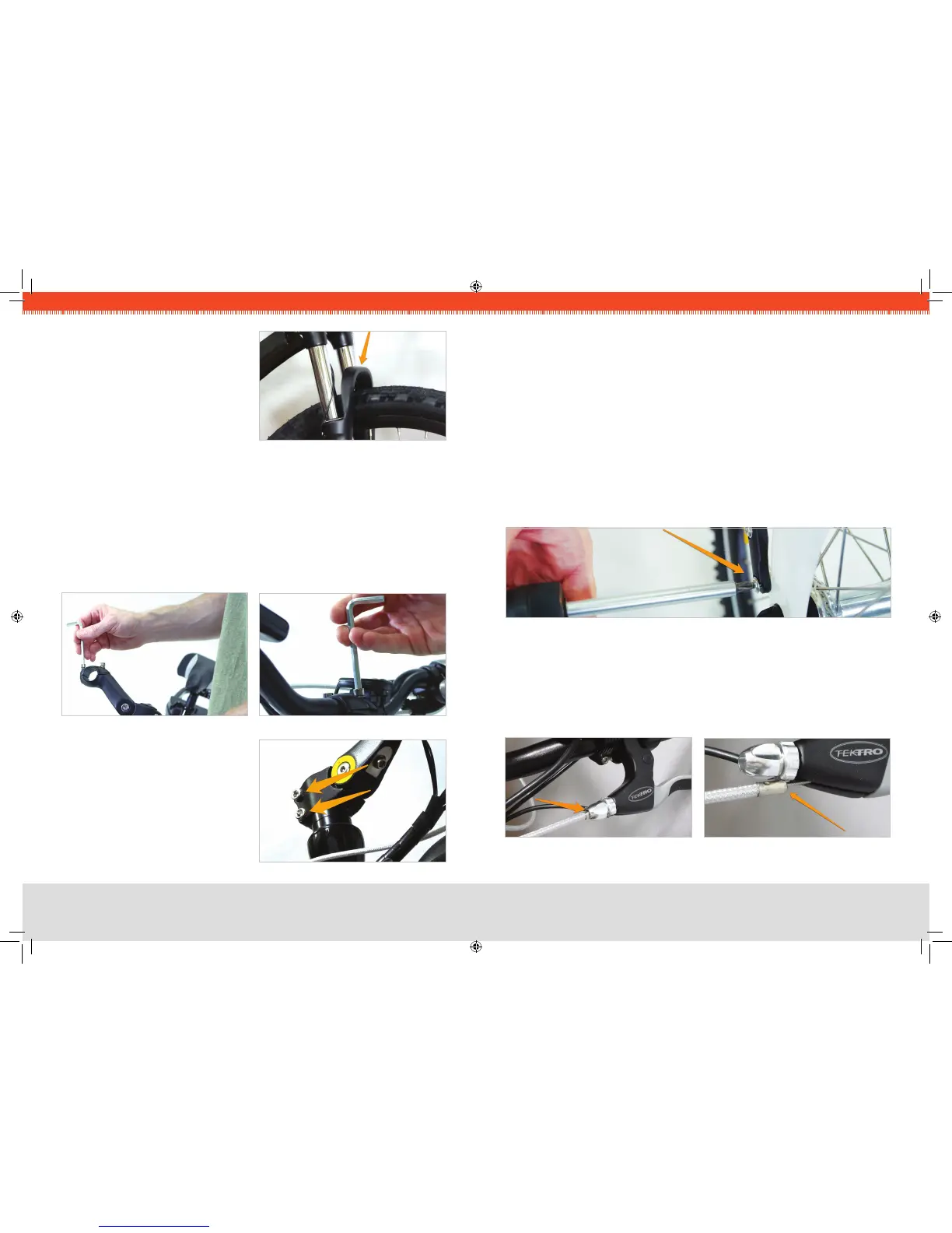
FIG 1C. BRAKE ARCH
CRITICAL
:
If the wheel is oriented
correctly, the brake arch (the painted
portion of the fork that bridges the two
fork legs) of the front fork should be
rotated FORWARD, as in Fig. 1C.
You can now lower the kickstand to keep
the bike upright for the remainder of the
assembly.
FIG 3. BARS IN CLAMPING BRACKET
FIG 2. CLAMPING BRACKET
STEP 3
:
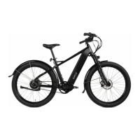
ATTACH FRONT FENDER & HEADLIGHT
Loosen and remove the pre-attached bolt that goes through the brake arch. 1.
Slide the fender into position, placing the silver tab that extends upward in front of the 2.
brake arch.
Re-insert the bolt from the backside. 3.
Bring the headlight into position in front of the brake arch, and screw the bolt into it. 4.
Tighten the bolt.5.
Remove the two Phillips screws near the front axle. Bring the black plastic tabs on 6.
the end of the wire struts up and bolt them in place using the screws. Repeat for each
side.
FIG 5. LOWER ORION FENDER
STEP 4
:
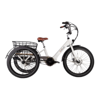
CHECK BRAKE INSTALLATION
Follow each brake cable, starting at the brake lever. Make sure that the brake housing 1.
(the sheathing that the cable runs through) is fully seated into the cylindrical hole
at the brake lever, as shown in the rst photo below. The second photo shows a
dislodged housing, which occasionally occurs during shipping and handling.
FIG 6. CORRECT BRAKE HOUSING FIG 7. INCORRECT HOUSING
FIG 4. STEM CLAMP BOLTS
Loosen the two bolts that clamp the 5.
handlebar stem to the steer tube, and
align the handlebars with the front
wheel.
Firmly re-tighten the two bolts. Note: 6.
Do not loosen the bolt located in the
top-center of the metal cap.