STEP 1
:
INSTALL FRONT WHEEL
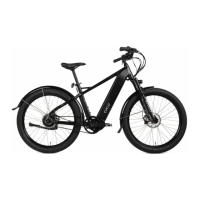
The front wheel is attached to the bike with a quick-release type of skewer. After 1.
locating the skewer, remove the nut on the end opposite the lever, and slide one of
the conical springs onto the skewer — wide-end rst.
Once the spring is against the lever’s nut, slide the skewer through the axle so that 2.
the lever is on the same side as the brake disc.
Now slide the second spring onto the skewer — narrow-end rst — then screw the 3.
nut partially back on.
Place the wheel into the fork, taking care to make sure the disc goes into the brake 4.
caliper.
With the axle fully seated into the fork dropouts (the slots that accept the axle), and 5.
the lever in the oPeN position, turn the nut to adjust the clamping pressure, and
swing the lever rearward to the CloSeD position, where you will feel noticeable
resistance. The lever should leave a slight impression in your hand, and the lever
should be parallel to the center-line of the bike when adjusted properly.
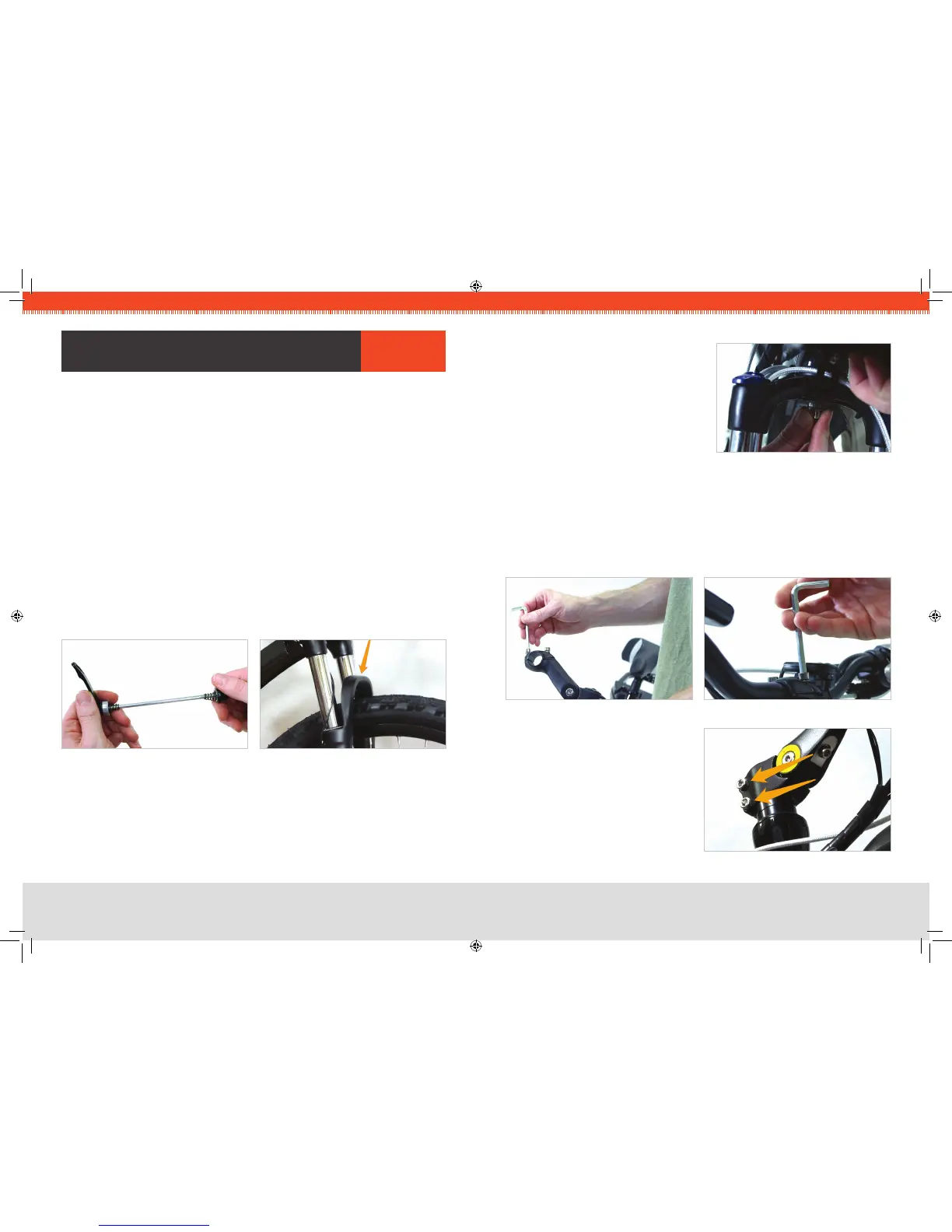
CRITICAL
:
If the wheel is oriented correctly, the brake arch (the painted portion of
the fork that bridges the two fork legs) of the front fork should be rotated FORWARD,
as in the photo.
You can now lower the kickstand to keep the bike upright for the remainder of the
assembly.
FIG 1A. QUICK RELEASE SKEWER FIG 1B. BRAKE ARCH
asseMBlY arIes
STEP 2
:
ATTACH FRONT FENDER
Locate the special threaded nut on the 1.
underside of the fork that has been
installed at the factory.
Using the wrench and bolt provided, 2.
install the fender from the underside of
the fork.
FIG 2. FENDER BOLT
STEP 3
:
ATTACH HANDLEBARS
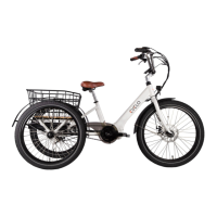
Remove the two bolts that hold the handlebar clamping bracket on. 1.
While taking care to keep the wires and cables as straight as possible, place the center 2.
of the handlebars into the bracket and replace the upper portion of the bracket.
Tighten the bolts evenly so there is equal space at the front and rear of the bracket. 3.
Firmly tighten both of the bolts.
FIG 4. BARS IN CLAMPING BRACKETFIG 3. CLAMPING BRACKET
FIG 5. STEM CLAMP BOLTS
Loosen the two bolts that clamp the 4.
handlebar stem to the steer tube, and
align the handlebars with the front
wheel.
Firmly re-tighten the two bolts. 5.
Note: Do not loosen the bolt located in
the top-center of the metal cap.