5
Stage 2 Tray Assembly
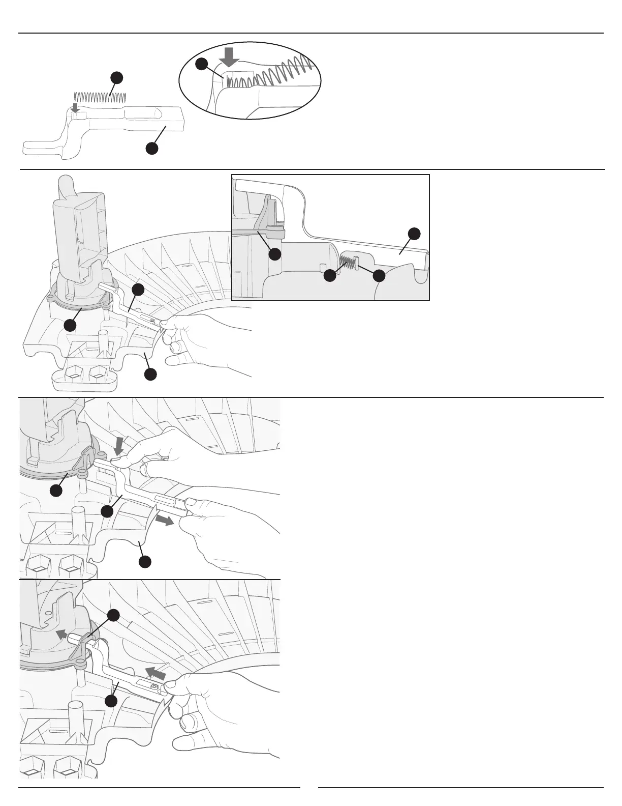
G
I
3. Slide one end of 1-3/4 inch (44.5 mm) spring G into the
spring notch H in leg lock I, as shown.
Note: Once the spring has been installed correctly, it will
stay in place. Repeat for all four leg locks.
4. Set one leg lock
I on the pylon ring D and on the tray A,
as shown.
Note: The Side Cutaway View above illustrates how the
spring G must rest against the spring tab J so the leg
lock I will operate properly.
I
D
A
H
J
D
G
I
Side Cutaway View
5. Push downward on the leg lock I (against the pylon
ring D and the tray A) while pulling it toward you until it
slides off of the pylon ring, as shown.
6. While holding the leg lock I, allow the spring to pull the
leg lock back toward the upper leg as you guide it through
the pylon ring D, as shown.
D
I
A
I
D

 Loading...