Do you have a question about the Everbilt THD1090 and is the answer not in the manual?
General safety precautions and warnings for operation and maintenance of the sump pump discharge kit.
Steps and considerations before starting the installation process, including checking package contents.
List of necessary tools for installing the sump pump discharge kit, including screwdrivers, saws, and safety gear.
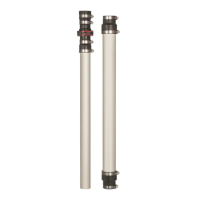
Detailed description of the components included in the Sump Pump Discharge Kit, identified by letters A, B, C, D.
Steps to follow when replacing an old discharge pipe system before installing the new kit.
Instructions for connecting the primary discharge pipe with the weep hole to the sump pump.
Steps for assembling and positioning the discharge pipes, coupling, and check valve components for installation.
This document is a Use and Care Guide for the Everbilt Sump Pump Discharge Kit, Item # 1002711124, Model # THD1090. It provides instructions for installation, safety information, and warranty details.
The Sump Pump Discharge Kit is designed for use with residential sump pumps, with a maximum pressure of 12 psi. Its primary function is to facilitate the discharge of water from a sump pump, preventing water accumulation in basements or other areas. A key design feature is a factory-drilled weep hole at the discharge connection, which is intended to prevent pump air lock, ensuring continuous and efficient operation. This weep hole is designed to leak, so it's important not to install the threaded fitting above a basin cover.
The kit consists of four main components: a discharge pipe with a weep hole (A), a coupling pipe (B), a pipe with a check valve (C), and an additional discharge pipe (D). These parts are assembled to create a complete discharge system for a sump pump. The check valve is a crucial component, as it prevents discharged water from flowing back into the sump basin once the pump turns off, maintaining the integrity of the drainage system.
For existing installations, the manual outlines a series of preparatory steps before installing the new kit. These steps include unplugging the pump, disconnecting the vent if the system is sealed, disconnecting the existing discharge pipe, removing the basin cover, and carefully removing the pump and its attached discharge pipe. Users are instructed to drain the discharge pipe above the old check valve into the basin or a bucket by pushing the flapper in the check valve, emphasizing caution due to potential messiness. Finally, the old check valve must be removed from the existing discharge pipe.
The installation process begins by attaching the discharge pipe with the weep hole (A) to the sump pump. This involves applying threaded tape to the discharge pipe and hand-tightening it into the pump's discharge opening. The pump is then placed in the basin, and the discharge pipe with the weep hole is aligned under the existing discharge pipe. The basin cover is replaced, ensuring the discharge pipe passes through its opening, though it should not be secured at this stage. A critical measurement is then taken: the distance between the end of the discharge pipe with the weep hole and the existing discharge pipe must be greater than 31 inches. If not, the existing discharge pipe needs to be cut to meet this minimum distance.
The next phase involves preparing the installation location. The coupling pipe (B) is slid onto the discharge pipe with the weep hole (A), followed by sliding the pipe with the check valve (C) into the coupling pipe (B). The pipe with the check valve (C) is then slid up and over the existing discharge pipe. If additional length is required, the additional discharge pipe (D) can be added to the existing discharge pipe. All hose clamps on the pipe with the check valve (C) and the additional discharge pipe (D) (if necessary) are tightened with a flathead screwdriver, ensuring not to exceed 15 in-lbs of torque. The coupling pipe (B) is positioned to cover at least 1 inch of both the discharge pipe with the weep hole (A) and the pipe with the check valve (C). Its hose clamps are also tightened with a flathead screwdriver, again not exceeding 15 in-lbs.
Finally, the existing discharge flange and vent are reattached to the cover as needed, and the cover is secured to the basin. The pump is then plugged in, and the system is cycled a few times to check for leaks. Any clamps found to be leaking should be tightened with a flathead screwdriver, adhering to the 15 in-lbs torque limit.
Maintenance features are primarily focused on periodic inspection and proper handling. Users are cautioned to periodically inspect the pump and system components to ensure the pump intake is free of mud, sand, and debris. This requires disconnecting the pump from the power supply before inspection. The manual also emphasizes that the motor housing is designed to operate at high temperatures and should not be touched during operation or disassembled.
Safety is a paramount concern throughout the manual. Several warnings and cautions are provided. Users are explicitly instructed to always disconnect power to the pump before servicing. When working with pumps, wearing safety goggles at all times is mandatory. A critical warning highlights the danger of handling the pump or motor with wet hands, while standing on a wet or damp surface, or in water. If the basement floor is wet, users are advised not to walk on the wet area until all power is turned off. If the shut-off box is in the basement, the electric company or local fire department should be called for instructions to shut off service to the house. Failure to follow this warning can result in fatal electrical shock.
Other safety precautions include releasing all pressure and draining all water from the system before servicing any component. Users are advised to know the pump and its applications, limitations, and potential hazards. The manual also stresses the importance of following all safety standards and local electrical codes.
The warranty covers defects in material and workmanship for a period of 12 months from the date of purchase, as determined by the original dated sales receipt. The manufacturer is not liable for products subjected to negligence, misapplication, improper installation, or maintenance, or if the product has been disassembled, modified, abused, or tampered with. The sole remedy under warranty is repair or replacement of defective systems at the manufacturer's choice, with the user responsible for labor and shipping charges. The warranty is non-transferable and excludes consequential, incidental, or contingent damages. It also excludes industrial, agricultural, commercial, and business usage. The warranty is valid only for products installed in the United States of America and Canada.
Customer service contact information is provided for questions, problems, or missing parts, available Monday-Friday from 8 a.m. to 7 p.m. EST, and Saturday from 9 a.m. to 6 p.m. EST, via a toll-free number (1-877-297-6069) or the Home Depot website.
| Brand | Everbilt |
|---|---|
| Model | THD1090 |
| Type | Battery Charger |
| Battery Voltage | 12 V |
| Color | Black |
| Cord Included | Yes |
| Indoor/Outdoor | Indoor |
| Number of Batteries Included | 0 |
| Output Voltage | 12V DC |
| Voltage (volts) | 12V |
| Input Voltage | 120V AC |
| Battery Type Compatibility | Lead Acid |
| Protection Features | Reverse polarity protection |