Do you have a question about the Evinrude 115 HP and is the answer not in the manual?
Defines DANGER, WARNING, and CAUTION terms used in the manual to indicate hazard levels.
Covers proper procedures, parts, torque, and tool usage for safe installation and operation.
Steps to remove the water pump from the driveshaft and its components.
Ensures the gasket surface is clean and smooth before reassembly.
Applies Adhesive 847 to the grommet and installs it into the impeller housing.
Coats the liner with grease and installs the impeller with the key slot facing out.
Applies Adhesive 847 to the seal groove and installs the special shaped O-ring seal.
Applies compound to the cup and installs the impeller plate gasket and plate.
Greases the O-ring and slides it onto the driveshaft to hold the impeller key.
Slides pump onto driveshaft, aligns key, and secures housing screws with specified torque.
Checks shift rod adjustment and installs gearcase with specified torque for mounting screws.
Starts outboard to verify water pump operation after installation.
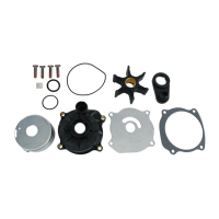
This document provides installation instructions for a water pump kit, part number 5007556, designed for Evinrude 115 and 130 HP outboard models from 2009 and newer. The primary function of this kit is to replace or repair the water pump assembly, which is crucial for the engine's cooling system. A properly functioning water pump ensures adequate water circulation through the engine, preventing overheating and maintaining optimal operating temperatures.
The installation process involves several steps, beginning with the disassembly of the existing water pump. This includes rotating the driveshaft counterclockwise to unlock the impeller key and removing the four impeller housing screws. Once the screws are removed, the water pump can be slid off the driveshaft, allowing for the removal of the impeller key, O-ring, impeller plate, and gasket. A critical step during disassembly is to ensure the gasket surface is thoroughly cleaned and smoothed, as any debris or unevenness can compromise the seal of the new components.
The assembly process for the new water pump kit is detailed with specific instructions for each component. It starts by applying a drop of Adhesive 847 in the seal ring groove at each of the four ribs within the impeller housing. A crucial warning is provided here: it is imperative not to allow any adhesive to enter the air bleed groove in the impeller housing. If this groove becomes blocked, the pump will lose its prime and fail to pump water effectively, leading to potential engine damage due to overheating.
Next, Adhesive 847 is applied to the flat side of the impeller housing grommet, which is then installed with the flat side facing down. The liner of the impeller housing is lightly coated with Triple-Guard grease. The impeller is then installed into the liner with a counterclockwise rotation, ensuring the slot for the impeller key faces outward. Following this, a thin bead of Adhesive 847 is applied in the seal groove, and the specially shaped O-ring seal is installed.
The exterior of the impeller cup is lightly coated with Gasket Sealing Compound before it is installed into the impeller housing. It is important to verify that the vent hole in the impeller cup remains open. Gasket Sealing Compound is then applied to both sides of a new impeller plate gasket, which is installed along with the impeller plate.
For the impeller O-ring, Triple-Guard grease is applied, and the O-ring is slid down the driveshaft, halfway over the installed impeller key, to temporarily hold the key in place. The sharp edge of the key should be the leading edge in clockwise rotation. The water pump is then slid down the driveshaft, aligning the impeller slot with the impeller key. The driveshaft is rotated to engage the key with the impeller, and the water pump is slid down over the key, ensuring the impeller key does not fall out of position. A critical note here emphasizes that the impeller must engage the impeller key; failure to do so can result in serious powerhead damage.
Once the water pump is fully assembled, the driveshaft is rotated counterclockwise by a quarter turn to unlock and release the impeller and key from the driveshaft. Subsequently, the driveshaft is pulled up and turned clockwise to lock the impeller to the shaft. This action is designed to increase pump efficiency by locking the impeller in a lower position on the driveshaft.
The impeller housing is then aligned with the gearcase. Gasket Sealing Compound is applied to the threads of the four impeller housing screws, which are then tightened to a torque of 60 to 84 in. lbs. (7 to 9.5 N·m).
Before installing the gearcase assembly onto the outboard, it is crucial to check the shift rod adjustment, referring to the appropriate Service Manual for guidance. The gearcase mounting screws are then tightened to specific torque values: 3/8 in. screws to 26 to 28 ft. lbs. (35 to 38 N·m), and 7/16 in. screws to 45 to 50 ft. lbs. (61 to 68 N·m). A warning highlights the importance of properly tightening all gearcase retaining screws, as failure to do so can lead to gearcase loss and loss of boat control at high speeds.
Finally, the outboard is started to check the water pump operation, ensuring that the new pump is functioning correctly and providing adequate cooling.
Maintenance features are embedded within the installation process, emphasizing the use of specific compounds like Triple-Guard Grease, Gasket Sealing Compound, and Adhesive 847 to ensure proper sealing, lubrication, and secure component placement. The instruction to replace any locking fastener if its locking feature becomes weak, and to use only authorized Evinrude/Johnson Genuine Parts for replacements, underscores the importance of using high-quality components for long-term reliability and safety. The document also stresses the importance of following torque wrench tightening specifications precisely, as incorrect tightening can lead to component failure or product malfunction.
The safety information provided at the beginning of the document is a key usage feature, guiding installers to prioritize safety. It advises that the kit should be installed by an authorized dealer, highlights the meaning of DANGER, WARNING, and CAUTION signal words, and emphasizes the importance of following common shop safety practices. It also warns against rushing or guessing during service procedures, as human error can have severe consequences. The document also states that if procedures or service tools not recommended in the instruction sheet are used, the installer alone is responsible for any resulting injuries or damage.
For the owner, the document advises saving the instructions as they contain important information for the use and maintenance of the engine. This ensures that owners have access to critical information regarding their water pump system, which can be vital for troubleshooting or future maintenance. The overall design of the instructions aims to provide a clear, step-by-step guide for a critical engine component, ensuring both proper function and longevity of the outboard motor.
| Horsepower | 115 HP |
|---|---|
| Type | Outboard Motor |
| Fuel Type | Gasoline |
| Steering | Remote |
| Gear Ratio | 2.00:1 |
| Cylinders | 3 |
| Shaft Length | 20 in; 25 in |