2
3.0 CELL INSTALLATION
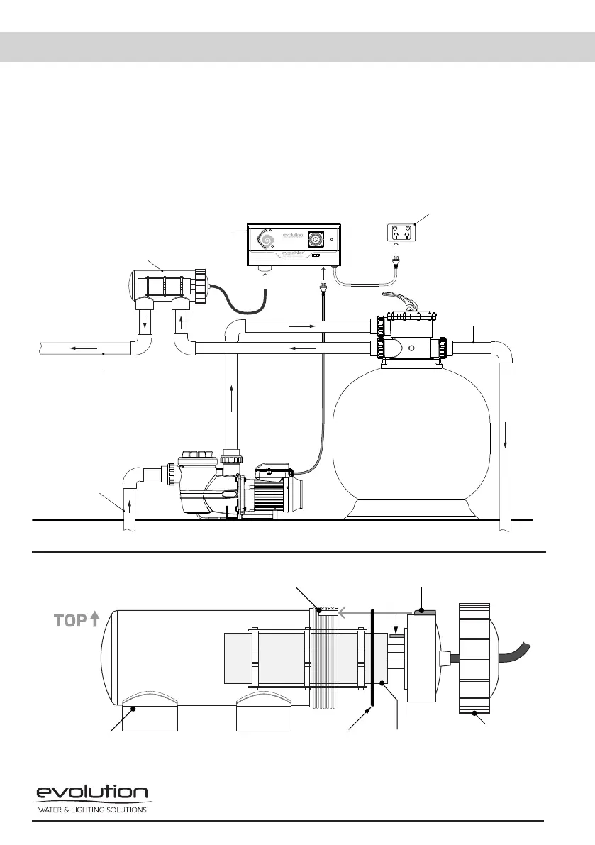
3.1 The electrolytic cell housing must be plumbed into the return line after the filter. Please
refer to the installation diagram, Fig.1, below for the preferred method. The cell housing has
allocations for either 40mm PVC pipe or 50mm PVC pipe with the use of the supplied PVC
reducing bushes.
3.2 If a heater is plumbed into the system, then the cell housing must be installed after the
heater in the return line to protect the elements or heat exchanger. If a solar heating system
is fitted, then the cell housing should be installed after the return line coming back from the
roof if it rejoins the main swimming pool return line.
CELL HOUSING
POWER PACK CONTROLLER
POWER OUTLET
TO POOL
RETURN
FROM POOL/
SKIMMER
BACKWASH LINE
Fig. 1
Fig. 2
Please note the installation position of the electrolytic cell for water probe positioning. Water probe faces top.
CELL HOUSING
CELL LOCATING LUG RECESS WATER PROBE* CELL LOCATING LUG
O-RING SEAL CELL CAP