4
5.0 OPERATION
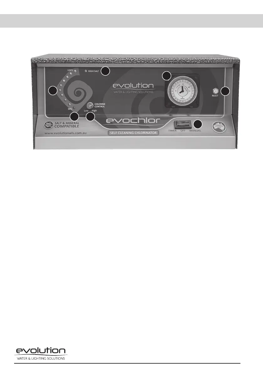
5.1 The control interface on the power pack consists of the following.
1. Chlorine Output LEDs
The output lights follow the curve of the Evolution logo. If the correct salinity level is
maintained in the water, then all ten lights will illuminate at full output (100%). Each light
represents 10% chlorine output. If all lights are not illuminated, then a higher salinity level will
be required. Make sure all salt is dissolved correctly before adding more. The chlorine control
(2 in Fig. 3) will increase or decrease the chlorine output to suit the chlorine requirements. If
all of the indicator lights flash, then there is a water flow fault.
2. Chlorine Control
The chlorine controller determines the amount of chlorine production. By simply turning the
control clockwise, chlorine output is increased, and by turning the control anti-clockwise,
chlorine output is decreased. Do not force the control past its stop as this will damage the
unit and void warranty.
3. High Salt Light
This light is a red warning indicator and will illuminate when the salt level in the swimming
pool is higher than 4500ppm. If this light is on, together with the ten output LED’s (1 in Fig. 3),
decrease the output by turning the chlorine control (2 in Fig. 3) anticlockwise until the high
salt (red light) goes off, and all ten chlorine output LEDs remain on. If this light is the only one
illuminated then the unit has gone into the over-temperature cutout and will reset once back
to normal running temperature.
4. Polarity Light
The polarity light is the first indicator light, 10% in the chlorine output array (1 in Fig.3). This
light will alternate between orange and green every reversing cycle, 4-12 hours. The factory
setting is a 12-hour cycle.
1
2
3
4
6
7
5
Fig. 3
 Loading...