13
www.evolutionpowertools.com
EN
OPERATING INSTRUCTIONS
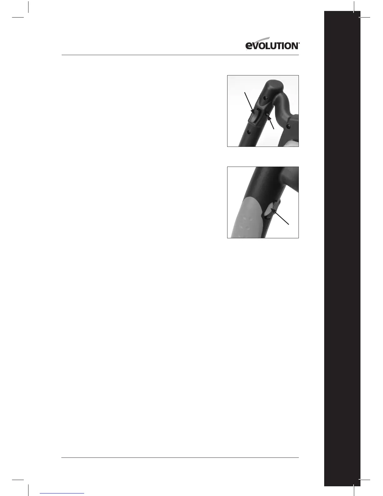
The On/O Trigger Switch (Fig. 4a)
Note: The Trigger Switch is ergonomically located on the
underside of the RH handle.
• Presstheswitchtostartthemotor.
• Releasetheswitchtostopthemotor.
Note: For continuous operation, and to provide operator
comfort, the trigger switch is tted with a ‘lock-on’ button.
• Presstheswitchtostartthemotorandthendepressthe
‘lock-on’ button (Fig. 4b) for continuous operation.
• Toswitchthemachineofromcontinuousoperation
gently squeeze the trigger switch and then release.
Speed Control
The Speed Control Adjustment Wheel (Fig. 5) is ergonomically
located on the inside of the LH handle where it can be easily
accessed by the thumb of a skilled operator.
Turning the Speed Control Adjustment Wheel alters the speed
of the motor through the range of approximately 250 – 750
rotations per minute (no load speed).
MIXING OPERATIONS
WARNING: This machine requires two (2) handed operation.
WARNING: The operator must observe all of the Safety
Instructions as outlined in this Instruction Manual. Failure to
do so could result in an increased risk of an accident or injury
to the operator.
• PositiontheMixingTubonahorizontal,stableand
secure surface.
• PlacethematerialstobemixedintheMixingTubin
accordance with the recommendations provided by the
manufacturer of the materials.
• ChecktheTwisterUnitandparticularlythesecurityofthe
attached Mixing Paddle.
• PlacetheMixingPaddleintheMixingTub.
• AdoptasecurestanceholdingtheTwisterUnitwithbothhands.
• WiththelowestspeedsettingselecteddepresstheTrigger
Fig. 4a + 4b
Fig. 5
(a)
(b)