EasyManua.ls Logo

Excalibur AL-XX70-B User Manual

Excalibur AL-XX70-B
16 pages
To Next Page IconTo Next Page
Page #1 background imageLoading...
Page #1 background image
INSTALLATION GUIDE
AL-XX70-B
Choose a discreet mounting location for the module and locations
for any accessories (siren, sensors, interface module, etc�)� Do not
mount the module yet
(you might anger the install gods)
Identify vehicle connection points and plan harness routing from
your mounting location� Avoid any moving vehicle parts or parts that
generate heat� Also avoid any sharp metal edges� See wiring details
on pages 3-10�
Cut system wires to length, prep your harnesses, and make all wire
connections to the vehicle�
NOTE: DATA/MUX WIRES ARE SENSITIVE and MUST BE SPLICED DIRECTLY
QUICK TAPS ARE NOT RECOMMENDED�
If you are using either of the system’s data ports for accessories
or modules using DBI protocol, connect these modules now and
con gure them for DATA MODE.
Perform VEHICLE LEARN (see pages 9 and 12 for instructions)�
This automatically matches the IGN/ACC/START outputs to the vehicle’s ignition switch,
auto-detects data protocols, chooses the best engine detection method, decides whether
neutral safety circuit is required, and allows you to quickly set engine and transmission
types� FASTER THAN PROGRAMMING!
Test the system for all functions.
Secure the module(s) and harnesses to the vehicle�
Reassemble the vehicle.
Test the system for all functions again
(keep the install gods happy)
Quick Reference - Installation Overview
1
2
3
4
5
6
7
8
9
WIRE DIAGRAM: CENTER OF THIS BOOKLET
FEATURE CHART: INSIDE BACK COVER
REMOTE START & SECURITY PERFECTED

Table of Contents

Question and Answer IconNeed help?

Do you have a question about the Excalibur AL-XX70-B and is the answer not in the manual?

Excalibur AL-XX70-B Specifications

General IconGeneral
BrandExcalibur
ModelAL-XX70-B
CategoryCar Alarm
LanguageEnglish

Summary

Quick Reference - Installation Overview

Choose Mounting Location

Select a discreet location for the module and accessories.

Plan Harness Routing

Identify connection points and route harnesses away from moving parts.

Connect System Wires

Cut wires, prep harnesses, and make connections, splicing data/MUX wires directly.

Connect Data Modules

Connect accessories using DBI protocol for data mode.

Perform Vehicle Learn

Automatically matches outputs, detects protocols, and sets engine/transmission types.

Test System Functionality

Test system functions before and after reassembly.

Secure and Reassemble

Secure modules and harnesses, then reassemble the vehicle.

Installation Considerations

General Installation Precautions

Verify circuits, route wiring safely, avoid airbag circuits, and work in ventilated areas.

6 Pin Main Wire Harness

Details for connecting the main 6-pin power harness, including wire functions and connections.

Wire Harness Connections

18 Pin Secondary Wire Harness

Describes connections for the 18-pin harness: ground, starter interrupt, brake, and sensor inputs.

4 Pin Secondary Wire Harness

Details connections for the 4-pin harness, including 3rd channel and alarm outputs.

3 Pin Satellite Relay Port (RED)

Explains connections for the RED 3-pin satellite relay port for start and ignition outputs.

Wiring Overview Diagram

4 Pin Analog Sensor Ports Overview

Lists input/output functions for analog sensor ports.

18 Pin Harness Connections Overview

Details connections for the 18-pin harness as shown in the diagram.

6 Pin Power Harness Connections Overview

Details connections for the 6-pin power harness in the diagram.

System Components and Procedures

Vehicle Learn Procedure

Step-by-step guide to configure system settings for the vehicle.

Data and Interface Ports

Explains functions of Green, Black Data, and BLADE ports for modules and programming.

Input/Output Ports

Details connections for BLUE Satellite Relay, Door Lock/Unlock, and Backup Battery ports.

Sensors and Modules

Describes connections for dual zone sensors, antenna, motion sensor, status light, and valet button.

System Configuration and Programming

Tach Programming

Procedure to learn the vehicle's tach signal for engine detection.

Transmitter Programming

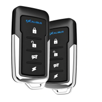
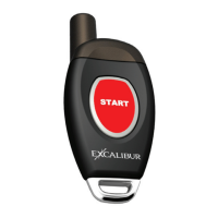
Method for programming additional or replacement remote transmitters.

Programmable Features Overview

Guide to manually changing and restoring system features and settings.

User and Installer Feature Tables

Detailed matrix of user and installer programmable features and their options.

Related product manuals