6
CONTROL FUNCTIONS
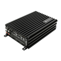
13. POWER Indicator
This LED will light up when amplifier works properly.
It will flash or shut down once amplifier in self-testing or malfunction.
14. ALARM Indicator
This LED will light up if amplifier has detected a fault or has shut down to protect itselvs.
This may caused - for example - at excessive heat, reverse polarity, short circuit or overload.
This case please turn off the amplifier, disconnect and resolve the problem before continue.
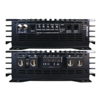
15. Speaker Terminals
Connect you speaker to these terminals with proper polarity.
Never connect the speaker cables with chassis ground, effect short circuit and damage amplifier.
Note: We have designed 8GA Terminals to fit Hollywood Energetic HPST Adapters = DUAL OUT
16. (+)12 Volt Battery Terminal
Connect this terminal with proper AWG size OFC Power Cable through a Fuse to the positive
terminal of the car battery or the positive terminal of an isolated external car audio battery.
WARNING: Always protect the Power Cable via Fuse less than 12inch (30cm) from battery terminal.
WARNING: HXA Amplifiers need external Fuse not less than 12inch (30cm) from Power terminal.
Please follow the maximum Fuse recommendation from Excursion HXA Specifications. See Page 2
Note: We have designed 4GA+0GA Terminals to fit Hollywood Energetic HPST Adapters = DUAL IN.
17. REM Terminal
This Remote terminal is to connect with headunit 12V remote output to turn ON/OFF the amplifier
according operating of headunit - if Turn ON/OFF Switch Option set on REM (see 3). If there are more
amplifier connected to this terminal it might be necessary, depending on REM performance of headunit,
to install an additional relay. If amplifier turn ON/OFF Mode is set DC or AUDIO, than 12V Remote is
not demanded, but REM terminal can provide and work as a 12V Remote Output distributor.
18. GND Terminal
This terminal is to connect directly to the frame of vehicle. Use shortest distance possible and equal
or larger AWG OFC Cable size than +12Volt Battery Cable. Asure frame has been cleaned to bar metal.
INSTALLATION PRECAUTIONS
Before you install the amplifier, investigate your car`s layout very carefully. Take special care when you
work near the gas tank, fuel lines, hydraulic lines and electrical wiring. Before making or breaking power
connections in your system, disconnect the car battery. Confirm that your headunit or other equipment is
turned off while connecting the input jacks and speakers terminals. If you need to replace the power
fuse, replace it only with a fuse identical to that suggested by this manual. Using a fuse of a different
type or rating may result in damage to your system or your amplifier which is not covered by warranty.
CONNECTING THE AMPLIFIER
Connect the amplifiers ground cable to a close, bare metal part of the frame or chassis.1.
Use a nut and bolt. The ground cable must be at least the same size as the +12Volt.
Connect the remote terminal to remote output of the head unit using upper 16GA wire if the remote 2.
turn ON/OFF Mode is set on REM.
Connect the fuse holder within 15" (30cm) of the car battery and run the selected cable from this fuse3.
to the amplifier via additional fuse within max. 15" (30cm) distance to the amplifier.
Connect all the inputs with high quality car audio cables to asure the performance of your amplifier.4.
Connect Remote Control if necessary 5.
Insert fuse(s) into the battery fuse holder(s).6.
 Loading...