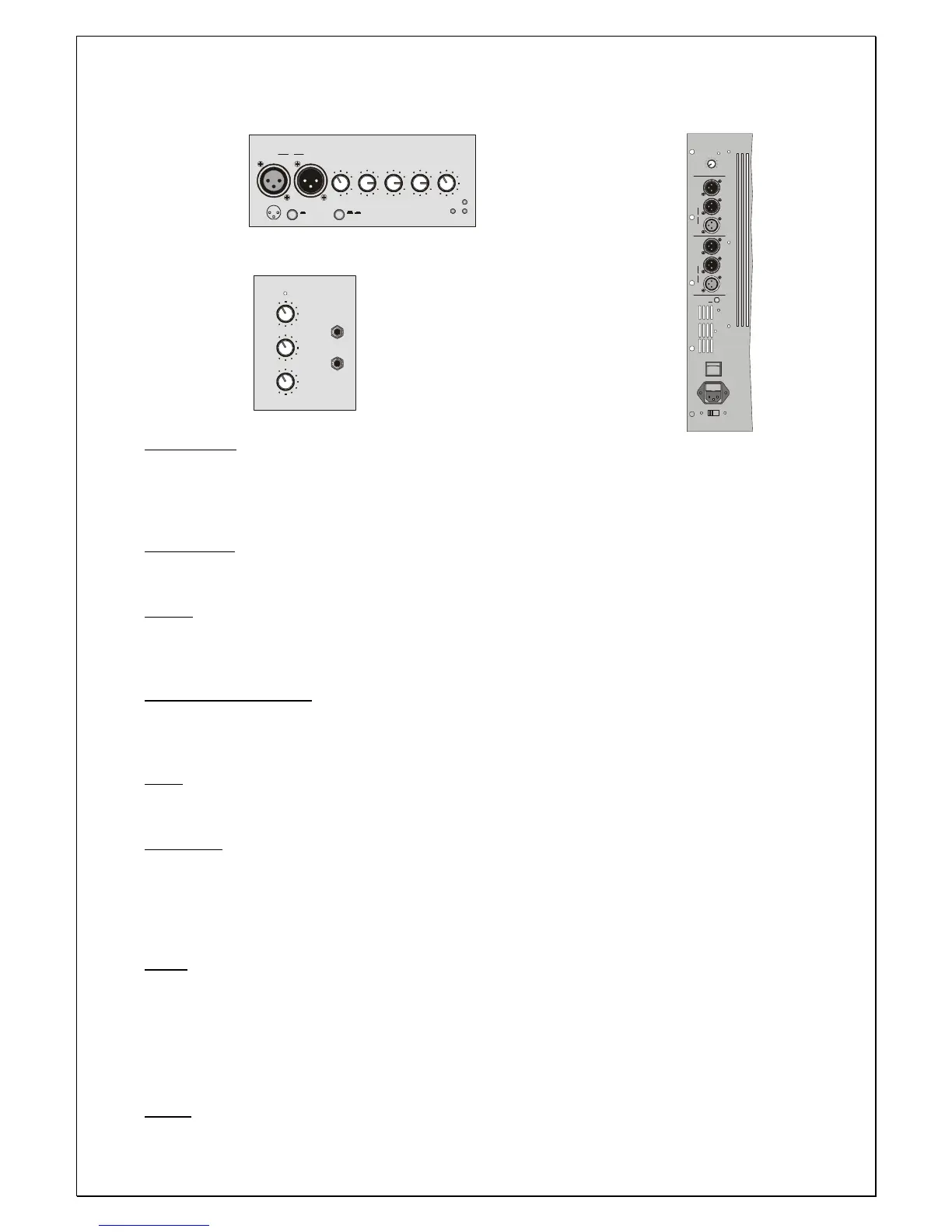
IN link OUT :
Input and output sockets, electonically balanced. The IN XLR socket allows connection of a dynamic
microphone at low impedance or of a pre-amplified signal such as a mixer line out, the OUT socket is
connected in parallel (link) with the input IN allowing multiple connections of more systems with the same
signal.
LINE / MIC :
Switch to select either MIC position if a microphone or a low frequency appliance is connected of high level
signal sources.
GAIN :
Regulates pre-amplification of the signal coming from the input IN, ensuring perfect operation of the
channel circuits. For a well-balanced again adjustment, set the Volume to approx ¾ clockwise, then adjust
the gain accordingly.
HIGH / MEDIUM / LOW:
3-band equalization to modify the sound tone. These controls are electronically post-gain and if boosted
can clip the channel: in this case adjust the gain control anticlockwise. When the potentiometers are set to
“0”, the tone remain unchanged.
VOL :
Volume potentiometer to control the channel signal level. Normally optimal channel circuit performance is
achieved with the knob positioned at approx. ¾ clockwise and the gain control set to the desired level.
GND LIFT :
2 position selector for separating the signal source ground and the amplifier ground circuits.
ON: The signal ground is electrically disconnected from the amplifier ground circuit (the chassis). If hum is
heard in the loudspeakers, the ON position breaks the ground loop, often the cause of this interference.
OFF: The ground of the input signals is electrically connected to the amplifier ground circuit (the chassis).
USE GROUND LIFT ONLY WITH BALANCED SIGNALS.
AASS:
Processor circuit which protects the transducers from excessive tensions, when the audio signal reaches
the dangerous threshold for the transducers, the A.A.S.S system automatically intervenes by reducing the
amount of signal within acceptable limits: the time reaction of the system is very fast. The speaker system
features two separate protection systems, both for the low frequency and the high frequency drivers, the
activation of these protections is recognisable through the “HF” and “LF” leds lighting up in the control
panel.
PWR :
Led signal to indicate the switching on of the system.
 Loading...