InstallationInstructions
1.Makesureallmovingpartshavestopped,parkingbrake
isengaged,andthekeyhasbeenremoved.
2.Raisethefrontendofthemachineandsupportwith
jackstands.
CAUTION
Raisingthemowerforserviceormaintenance
relyingsolelyonmechanicalorhydraulic
jackscouldbedangerous.Themechanicalor
hydraulicjacksmaynotbeenoughsupport
ormaymalfunctionallowingtheunittofall,
whichcouldcauseinjury.
DoNotrelysolelyonmechanicalorhydraulic
jacksforsupport.Useadequatejackstands
orequivalentsupport.
3.Ifthemowerhasbeenused,scrapetheundersideof
themowerdeckclean.
4.Removeandretaintheexistingbladesfromtheunit.
Keepthehardwaretoinstallthemulchblades.
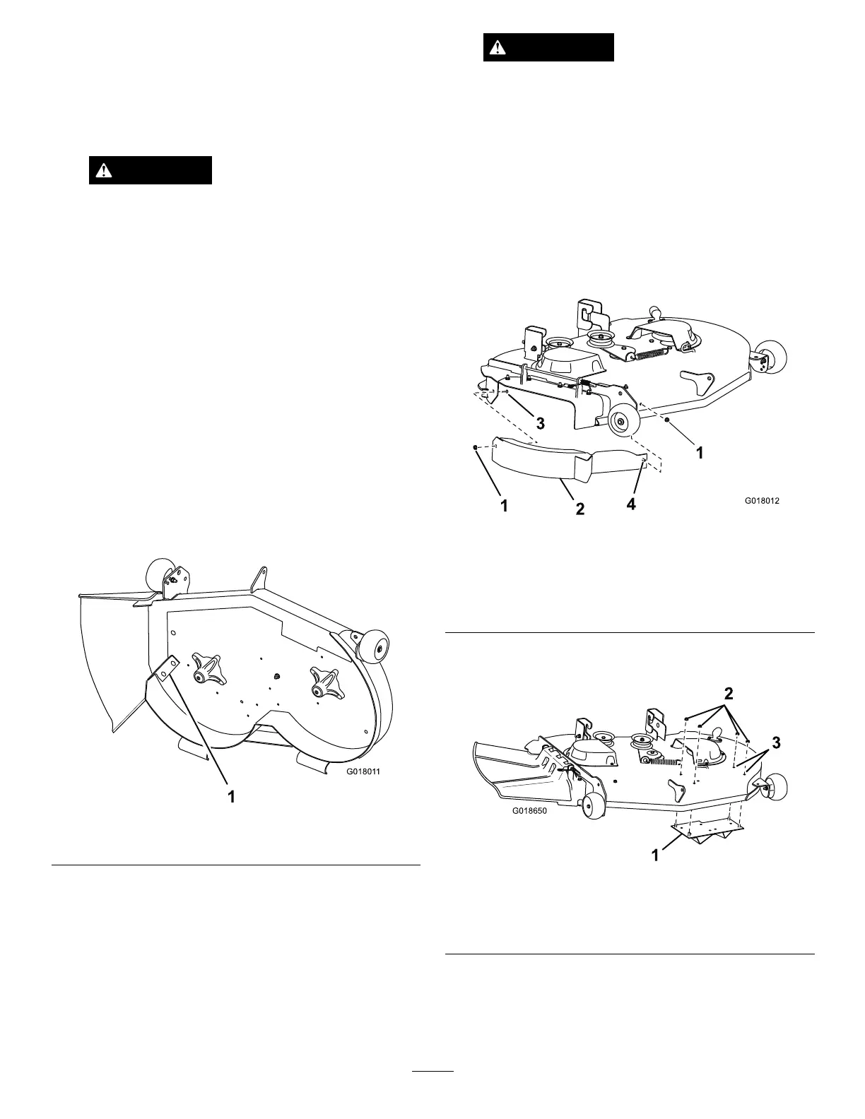
5.Removeandretaintheexistingdischargebafeand
mountinghardwareasshowninFigure3.
Note:Retainthedischargebafeforreuseifthe
mulchkitisremoved.
Figure3
1.Existingdischargebafe
6.Reinstallthemountinghardware,fromstep5,into
theholesinthedeckwherethedischargebafewas
installed.
WARNING
Openholesinthemowerexposeyouand
otherstothrowndebriswhichcancause
severeinjury.
•Neveroperatethemowerwithouthardware
mountedinallholesinthemowerhousing.
•Installthehardwareinthemountingholes
whenyouremovethemulchingbafe.
7.LooselyinstallthebafeassemblytotheRHsideof
themowerdeckusing5/16-18x3/4inchcarriagebolt
andtwo5/16inchangenutsasshowninFigure2and
Figure4.
Figure4
Dischargedeectorremovedforclarity
1.5/16inchangenut3.5/16-18x3/4inchcarriage
bolt
2.Bafeassembly
4.Weldedpost
8.Removethetwoplugboltsandnutsfromthedeckas
showninFigure5.
Figure5
1.Kickerplate3.Removeplugboltsand
nuts
2.5/16inchangenut
9.SecurethekickerplatetotheLHsideofthemower
deckusingfour5/16inchangenutsasshownin
Figure2andFigure5.
10.Tightenallhardware.
3