380460/380462-en-GB_v2.5 8/15
3
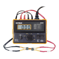
Operation
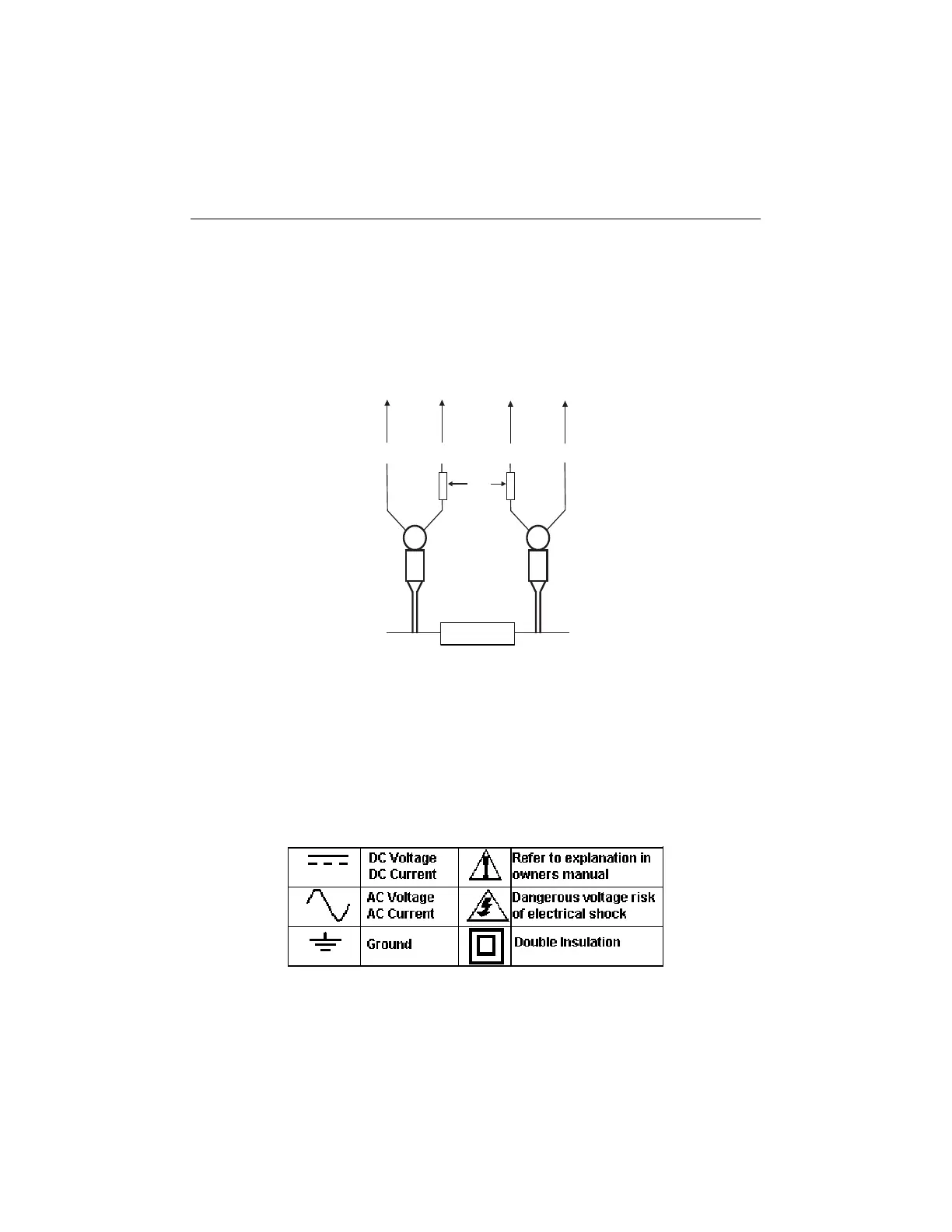
Basic Principles of 4-wire Measurements
For each range, the meter provides a specific amount of test current (refer to General Specifications)
which flows from the HI to the LO meter terminal and therefore from the HI to the LO clip lead (Refer
to the diagram). This is the current that ultimately passes through the device under test (RX in
diagram below).
Once the test current is applied to the device under test, clip leads Rx1 & Rx2 measure the voltage
drop across the device under test. The following equations detail how the meter accomplishes its
measurement tasks.
Measurement Equations
Vx = Is x Rx;
Where Vx is the voltage (measured by the meter) across the device under test; Is is the test current;
Rx is the resistance of the device under test. From Vx = Is x Rx, the meter moves to the next step
which is: Rx = Vx/Is. With this equation the meter determines the resistance of the device under test.
Note that the measured resistance (Rx1 & Rx2) is not affected by stray resistance since the test
current is supplied directly to the device under test. This is the advantage of the 4-wire Kelvin lead
configuration over 2-wire methods which introduce errors into low resistance measurements.
International Symbols
LO
HI
Rx1 Rx2
White
bands
Rx
Device under test
To Meter
www.GlobalTestSupply.com
Find Quality Products Online at: sales@GlobalTestSupply.com