380950 V1.0 6/07 5
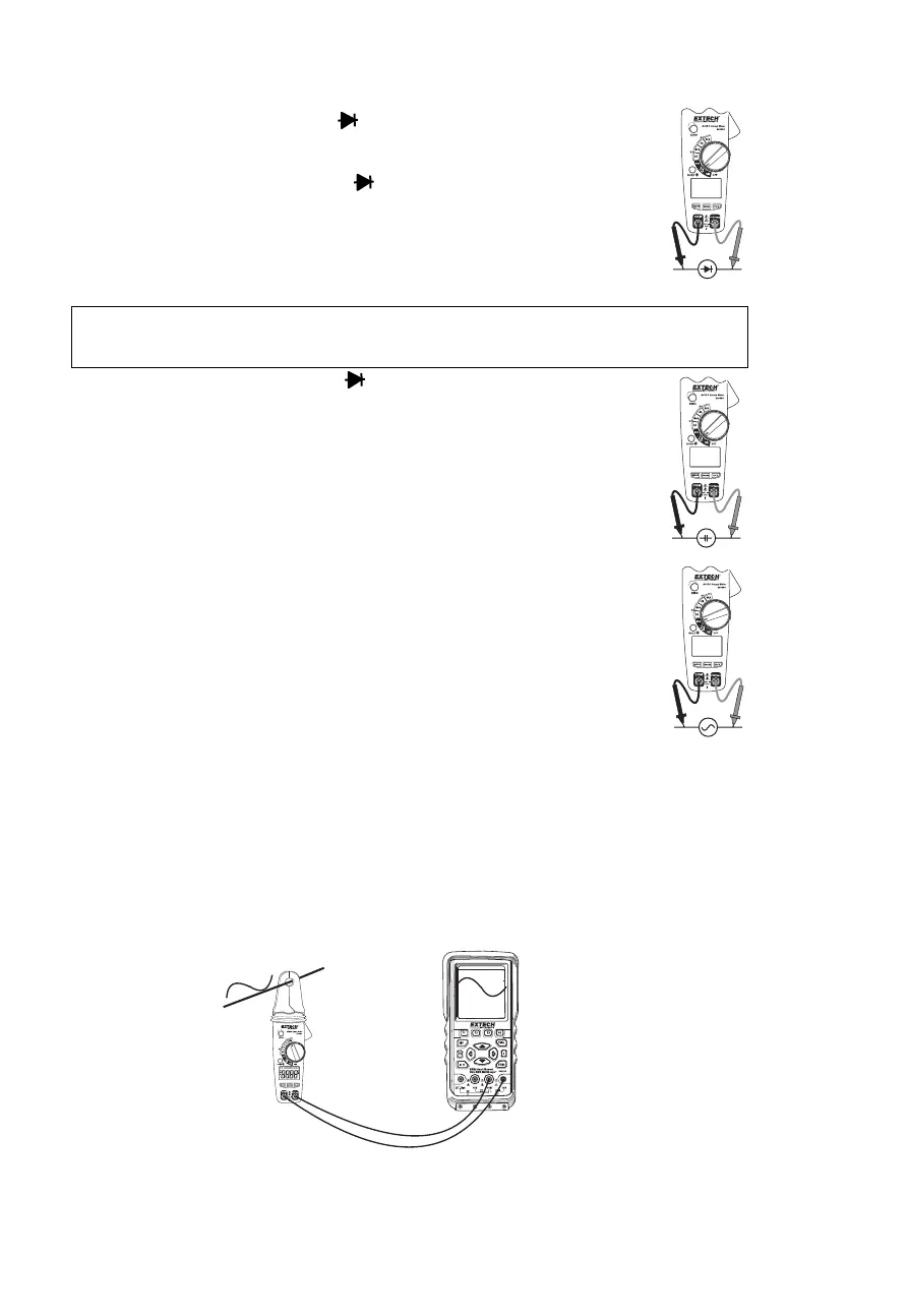
Diode Test
1. Turn the rotary switch to the
Ω •))) CAP position.
2. Insert the black test lead banana plug into the negative (COM) jack
Insert the red test lead banana plug into the positive (VΩ Hz) jack.
3. Push the mode button to indicate on the display.
4. Touch the test probes to the diode under test. Typically for a normal diode,
forward voltage will indicate 0.4V to 0.7V. Reverse voltage will indicate
“OL”. Shorted devices will indicate near 0V and an open device will indicate
“OL” in both polarities.
Capacitance Measurements
Warning: To avoid electrical shock, disconnect power to the unit under test and
discharge all capacitors before taking any capacitance measurements. Remove the
batteries and unplug the line cords.
1. Set the function switch to the Ω •))) CAP position.
2. Push the mode button to indicate nF on the display.
3. Insert the black lead banana plug into the negative (COM) jack
Insert the red test lead banana plug into the positive (VΩHz) jack.
4. Press the ZERO key to null the meter display.
5. Touch the test probe tips to the capacitor you wish to check.
6. Read the capacitance value on the display.
Frequency or % Duty Cycle Measurements
1. Turn the rotary switch to the Hz % position.
2. Insert the black test lead banana plug into the negative (COM) jack and the
red test lead banana plug into the positive (VΩ Hz ) jack.
3. Select Hz or % with the HZ/% button.
4. Touch the test probe tips to the circuit under test.
5. Read the frequency on the display.
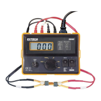
Analog Signal Output
1. Turn the rotary switch to the DCA or ACA ranges.
2. Insert the black test lead banana plug into the negative (COM) jack and the red test lead
banana plug into the positive (VΩ Hz) jack.
3. Connect the test leads to a multimeter, oscilloscope or chart recorder inputs.
4. Press the trigger to open the jaw. Fully enclose the conductor to be measured.
5. The analog voltage signal is output to the measuring device.
Note: When measuring DCA, the output signal is DCV. When measuring ACA, the output
signal is both ACV and DCV.