48VFL & 96VFL v1.2 07/13
If A2FU=None, it means alarm function is cancelled.
dif.L, bd.Hi, bd.Lo
t.on, t.oFF
Alarm 2 mode. Refer to alarm mode section for details
none, Stdy,
Lath, St.La
Controller address. For use with PC RS-485 interface 0 - 255 0
Baud rate. 2.4k=2400bps, 4.8k=4800 bps, 9.6k=9600 bps,
19.2k=19200 bps
2.4k, 4.8k
9.6k, 19.2k
9.6k
Code
Description
Range
Default
Low Scale of Linear Input
-1999~9999(-199.9~999.9) 0.0
High Scale of Linear Input
-1999~9999(-199.9~999.9) 100.0
Scaling for Linear Input
1.
Press and hold the UP and DOWN keys simultaneously for 5 seconds to access the “LnLo” parameter.
2. Adjust “LnLo” setting to correspond to the low scale; after adjustment, press
key once to
access “LnHi”
3.
Adjust “LnHi” setting to correspond to the high scale
; a
fter adjustment press
key once to exit
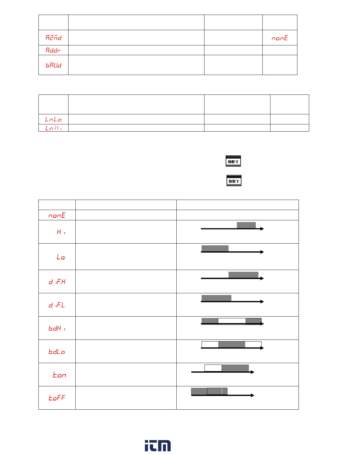
ALARM FUNCTION
A1FU/A2FU ALARM TYPE ALARM OUTPUT OPERATION
Alarm function OFF Output OFF
Process high alarm
▲ PV
SP
Process low alarm
▲ PV
SP
Deviation high alarm
▲ PV
SP+ALSP
Deviation low alarm
▲ PV
SP+ALSP
Band high alarm
OFF
▲ ▲ ▲ PV
SP-ALSP SP SP+ALSP
Band low alarm
OFF OFF
▲ ▲ ▲ PV
SP-ALSP SP SP+ALSP
On-timer
ALSP
▲ ▲ PV
SP
Off-timer
ALSP
▲ ▲ PV
SP
ALARM MODE
w ww. . com
information@itm.com1.800.561.8187