EasyManua.ls Logo

Extech Instruments 96VFL User Manual

Extech Instruments 96VFL
37 pages
To Next Page IconTo Next Page
Page #1 background imageLoading...
Page #1 background image
USER MANUAL
Process PID Controllers
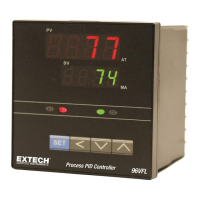
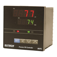
Model 96VFL DIN Controller
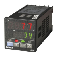
Model 48VFL DIN Controller

Table of Contents

Other manuals for Extech Instruments 96VFL

Questions and Answers:

Extech Instruments 96VFL Specifications

General IconGeneral
Output Power<1mW
Laser ClassClass II
Power Source2 x AAA batteries
Measurement Range0.05 to 100 m
Operating Temperature0 to 40 °C

Summary

Introduction to Extech Process Controllers

Controller and Input Wiring

Information on connecting the controller's inputs, outputs, and power.

Display Functions

Explanation of the PV and SV display digits on the front panel.

Output Options

Description of control and alarm output options and their functions.

Configuration and Tuning

Overview of programming menus and importance of controller tuning.

Customer Support Information

Information on customer support, documentation, and warranty.

Safety Precautions

Safety Warnings

Critical safety information and warnings for installation, wiring, and maintenance.

Panel Installation Guide

48VFL Model Mounting

Step-by-step guide for mounting the 48VFL model into a panel.

96VFL Model Mounting

Step-by-step guide for mounting the 96VFL model into a panel.

Controller Wiring Procedures

Safety Wiring Considerations

Crucial safety advice for wiring to prevent injury and damage.

AC Power Wiring

Specific instructions for connecting AC power to the 96VFL and 48VFL models.

Thermocouple Input Wiring

Wiring details for connecting thermocouple sensors to the controller.

Analog Input Wiring

Wiring instructions for optional 4-20mA analog input signals.

RTD Input Wiring

Wiring guide for connecting RTD sensors (2, 3, or 4 wire).

Control Relay Wiring

Wiring diagrams and explanations for control relay outputs (OUT 1, OUT 2).

Pulsed DC Trigger Output Wiring

Instructions for wiring the optional pulsed DC trigger output.

Analog Output Wiring

Details on wiring optional analog outputs (4-20mA).

Alarm Relay Output Wiring

Wiring instructions for the alarm relay outputs.

Product Description and Features

96VFL Front Panel Overview

Detailed description of the 96VFL model's front panel elements and indicators.

48VFL Front Panel Overview

Detailed description of the 48VFL model's front panel elements and indicators.

Keypad Descriptions

Explanation of the functions of each key on the controller's keypad.

Display Descriptions

Explanation of the Process Variable (PV) and Setpoint (SV) displays.

Status Indicators

Explains the 'A1', 'A2' Alarm, 'C1', 'C2' Control, 'MA' Manual, and 'AT' Auto Tune status LEDs.

Process Control Methods

Input/Output Connections

Guidance on connecting various input and output types to the controller.

Controller Programming

Importance of programming and tuning for optimal process control.

Control Output Types

Primary relay, secondary relay, and DC trigger output functionality.

Analog Output Option

Details on using the 4-20mA analog output option for process control.

ON-OFF Control

Explanation of the simple ON-OFF control method and hysteresis.

PID Control Basics

Introduction to PID control and its three key elements (P, I, D).

PID Time Proportioning Control

How PID control is applied to relay outputs using time proportioning.

Proportional Control Considerations

Factors affecting proportional control, including Proportional Band (Pb).

Dead-Band Considerations

How the dead band (db) parameter controls simultaneous ON states of outputs.

Programming Menu Navigation

Programming Menu Basics

General information on navigating and using the controller's programming menus.

Navigating the Menus

Step-by-step instructions for accessing and moving through programming menus.

User Level Programming Menu

Key User Settings

SP, A1SP, A2SP, and Auto Tune parameter configurations.

Manual Control Settings

Manual Control (HAnd) and Output Level (oUtL) parameters.

Soft Start Programming Menu

Soft Start Parameters

Soft start setpoint and output level configurations.

Ramp-to-Setpoint Overview

Configuration and overview of the Ramp-to-Setpoint feature.

PID Tuning Programming Menu

PID Tuning Parameters

Proportional, Integral, and Derivative settings for PID control.

Cycle Time and Hysteresis

Ct (Cycle Time) and HYS 1/2 (Hysteresis) parameter settings.

Alarm Hysteresis and Dead Band

Alarm hysteresis (A IHY, A2HY) and dead band (db) parameter settings.

Offset and Parameter Lock

Setpoint offset (SPOF), PV offset (PYOF), and Parameter Lock (LOCY).

Option Programming Menu

Option Settings

Input type, control action, and limit configurations.

Alarm and Timer Settings

Alarm function, mode, and timer format settings.

Input Type Selection Details

Detailed guide on selecting the 'TYPE' parameter for hardware configuration.

Low and High Limit Considerations

Explanation of how Low/High Limits affect the Proportional Band and operation.

Alarm Function and Modes

Alarm Function Lists

Lists and describes various alarm functions like High, Low, and Deviation.

Alarm Standby and Latch Modes

Explains Standby and Latch modes for alarm behavior.

ON-OFF Alarm Timers

How alarm relays function as ON/OFF timers.

Linear Input Programming Menu

Linear Input Low Display Setting

LnLo: Linear input low display setting for analog inputs.

Linear Input High Display Setting

LnH: Linear input high display setting for analog inputs.

Control Modes and Tuning

Automatic Tuning Procedure

Procedure and parameters for automatic PID tuning.

Automatic Control Mode

Normal operation where the controller automatically adjusts output.

Manual Control Mode

How to manually adjust control outputs from 0.0 to 100.0%.

Troubleshooting Guide

Common Error Codes

Troubleshooting for OPEN, AdEr, and At Er errors.

Operational Troubleshooting

Resolving issues with keypad, value stability, output, and display.

Data Integrity Issues

Troubleshooting abnormal process value changes and data loss.

Heating Process Example

Controlling Oven Temperature

Steps to control oven temperature using the controller.

Programming for Heating Example

Specific parameter settings for the heating process example.

Technical Specifications

General Specifications

Overall specifications including display, power, and dimensions.

Thermocouple Input Specifications

Detailed specifications for thermocouple input types and ranges.

RTD Input Specifications

Detailed specifications for RTD input types and ranges.

Analog Input Specifications

Detailed specifications for analog input types and ranges.

Control Output Specifications

Specifications for relay and DC trigger control outputs.

Manual Tuning Specifications

Specifications for manual tuning parameters (Pb, Ti, Td, etc.).

Alarm Output Specifications

Specifications for alarm relay outputs.

Analog Output Specifications

Specifications for analog output.

Warranty and Services

Two-year Warranty Information

Information regarding the two-year limited warranty.

Calibration and Repair Services

Details on calibration and repair services offered.

Customer Support

Related product manuals