29 VFL Series User Manual v2.3 12/20
ALARM FUNCTION GRAPHIC DESCRIPTIONS
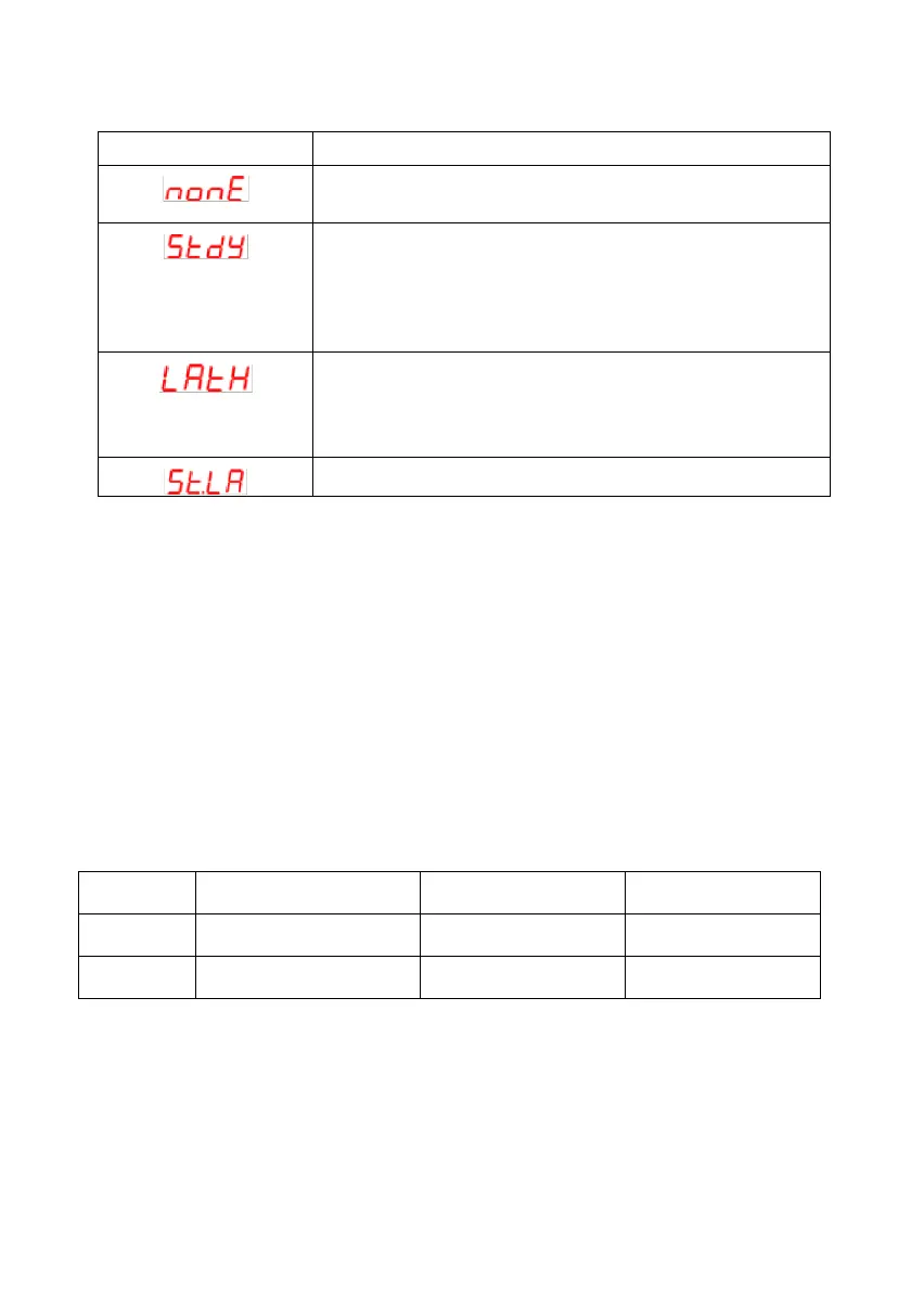
Each alarm option, listed in the AxFu parameter lists above, is illustrated below.
• ON and OFF: The output status of the alarm relay. The hollow circle represents an
‘ON’ relay state. The black filled circle represents an ‘OFF’ relay state.
• SV: Setting Variable
• AxHY: Hysteresis of the Alarm.
• AxSP: Alarm Setpoint.