7 VFL Series User Manual v2.3 12/20
4. Wiring
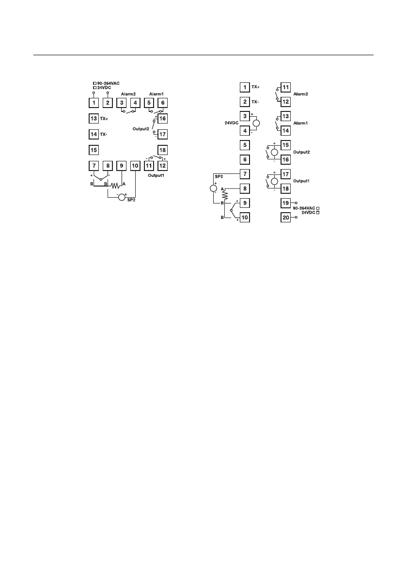
FIGURE 4.1: SERIES VFL WIRING (48VFL ON LEFT, 96VFL ON RIGHT)
4.1 WARNING! Wiring Safety Considerations
Before you start wiring, please confirm the hardware options installed in your controller:
Input (TC, RTD, or Analog); Outputs (relay, analog, or dc trigger), number of alarm and
control outputs, etc.).
Your wiring plan must match your unique hardware options. For example, if you jump
120Vac power to output terminals when you have a 4-20ma output circuit installed, serious
damage to the controller and personal injury can result.
The controller options label matches the model number ordered, contact Extech if there is
any uncertainty. Improper wiring can cause personal injury and damage to the controller
and connected equipment.
To avoid noise induction, keep input signal wires away from instrument power lines, load
lines and power lines of other electrical equipment.
4.2 AC Power Wiring
96VFL: Terminals 19 and 20 can safely accept 90 to 260VAC 50/60Hz (24VDC is optional).
48VFL: Terminals 1 and 2 can safely accept 90 to 260VAC 50/60Hz (24VDC is optional).
4.3 Thermocouple Input Wiring
96VFL: Terminal 9 (-) and terminal 10 (+).
48VFL: Terminal 8 (-) and terminal 7 (+).
4.4 Analog Input (4-20mA) Wiring
96VFL: Terminal 9 (-) and terminal 10 (+).
48VFL: Terminal 8 (-) and terminal 7 (+)