11 VFL Series User Manual v2.3 12/20
5.2 48VFL Front Panel
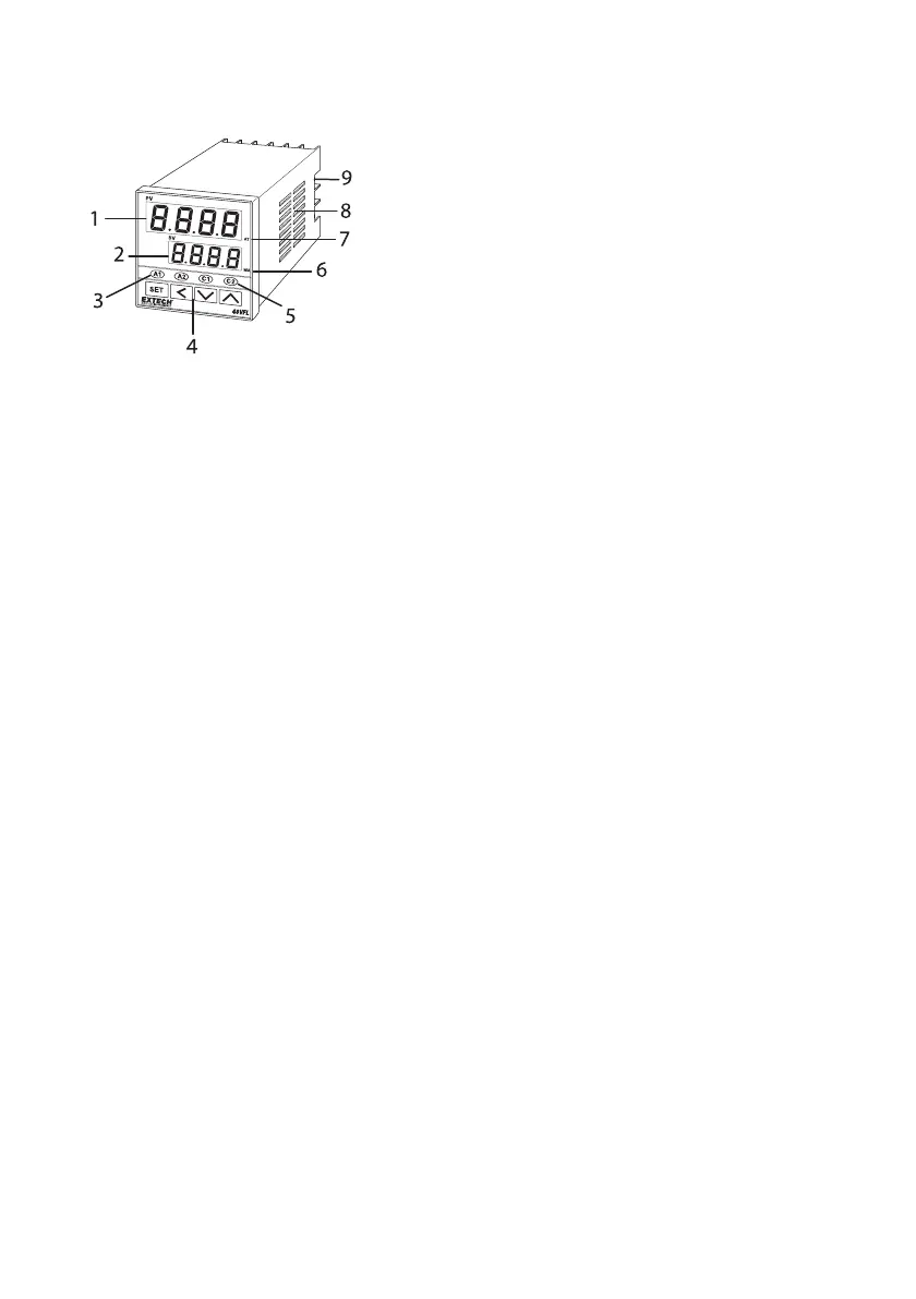
FIGURE 5.2: 48VFL FRONT PANEL
1. Process Variable (PV) display digits (red) show the process input.
2. Setting Variable (SV) display digits (green) show the programmed setpoint.
3. Alarm 1 (A1) and Alarm 2 (A2) relay status indicators.
4. Programming keypad: Set, Shift (<), Down arrow, Up arrow (left to right). See dedicated
section below.
5. Control Output 1 (C1) and Control Output 2 (C2) status indicators.
6. MANUAL control mode status (rightmost decimal flashes on SV display).
7. AUTO TUNING mode status (rightmost decimal flashes on PV display).
8. Ventilation holes (do not obstruct airflow)
9. Rear screw terminal block.
5.3 Keypad Descriptions
SET Key
• Used to access and scroll through Menu 1 (User level) parameters. Used to scroll
through menus 2, 3, 4, and 5 also, once they are accessed (see combination keystrokes
paragraph below, and the Programming menu sections, for complete details).
• Long press (5 seconds) to reset an Alarm Timer.
SHIFT Key (<)
• Short press to access the SV setting mode, then press again to select a digit for editing.
Change a digit’s value with the arrow keys, and then press SET to confirm.
• Long press (5 seconds) to start the Auto Tuning utility.
• Long press (5 seconds) to abort an Auto Tune session.