8 VFL Series User Manual v2.3 12/20
4.5 RTD Input Wiring
Wire a 2-, 3-, or 4-wire RTD as shown in the diagrams below.
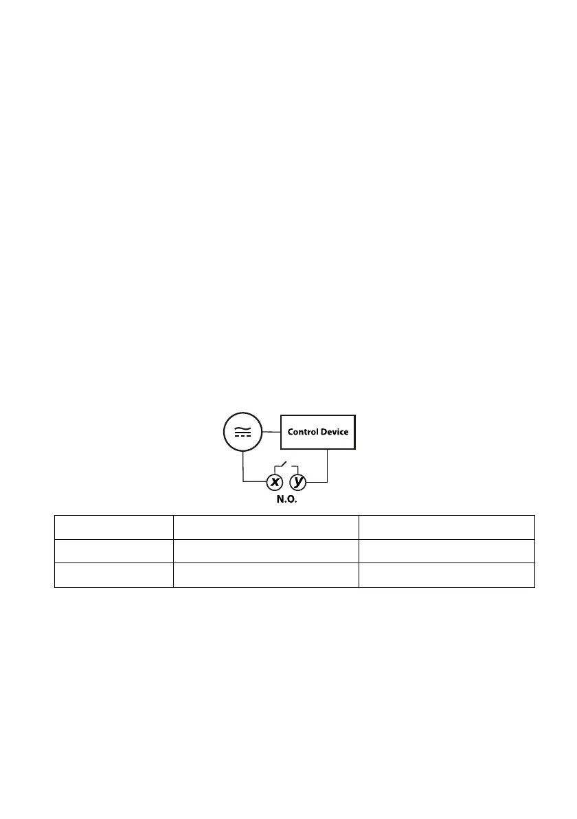
4.6 Control Relay Wiring
A basic VFL controller includes one control relay (OUT 1), the second control output (OUT 2)
is optional.
Control relay outputs are single-pole, single-throw (normally open N.O.) mechanical
switches. When the controller activates a control relay, the normally open switch closes. The
relay itself does not provide power. AC or DC power must be wired in series with the relay
and control device as shown below. Relays are rated 5 Amps @ 110V AC or 24VDC (Resistive
Loads).
In the diagram below terminals ‘x’ and ‘y’ represent the VFL rear terminal designations, see
the table below for the specific terminal numbers.
FIGURE 4.2: NORMALLY OPEN (N.O.) CONTROL OUTPUT WIRING