9 VFL Series User Manual v2.3 12/20
4.7 Pulsed DC Trigger Output Wiring
The DC Trigger output delivers 24V DC (approx.) across the same terminals that are used for
the relay outputs. See Control Relay terminals table above. The DC Trigger output is ON or
OFF, not linear as the 4-20mA analog output.
4.8 Analog Output Wiring
Analog outputs are optional. Analog outputs are available across the same terminals that
are used for the control relay outputs. See terminal designations below. Parameter ‘Ct’ (PID
Menu 3) must be set to ‘0’ when using an analog output.
96VFL Output 1: Terminal 18 (-) and terminal 17 (+).
96VFL Output 2: Terminal 16 (-) and terminal 15 (+).
48VFL Output 1: Terminal 11 (-) and terminal 12 (+).
48VFL Output 2: Terminal 17 (-) and terminal 16 (+).
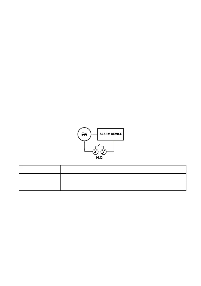
4.9 Alarm Relay Output Wiring
One relay is supplied in a standard VFL controller, the second alarm is optional. Alarm relays
are normally open (N.O.) single-pole single-throw mechanical switches, but their logic state
can be reversed (to normally closed N.C.) in the A1Fu or A2Fu programming menu. See all
the alarm programming menus for more information on alarm functions, specialty modes,
and event/soak timers.
Alarm relays do not supply power and should be wired in series with power. Alarm relays
are rated for 3 Amps @ 110VAC or 24VDC (resistive loads) maximum.
In the diagram below terminals ‘x’ and ‘y’ represent the VFL rear terminal designations, see
the table below the figure for the specific terminal numbers.
FIGURE 4.3 - ALARM RELAY OUTPUT WIRING