10 VFL Series User Manual v2.3 12/20
4.10 Optional 24Vdc ‘Loop Power’ Supply (96VFL)
On the 96VFL, terminals 3 (+) and 4 (-) offer an optional 24Vdc power supply that can be used
to provide ‘loop power’ to your process.
5. Product Description
The numbered call-out items below describe the basic operational functions for the displays,
indicators, and keys. Advanced uses are explained in the Keypad Descriptions and Display
Descriptions sections, and throughout this manual.
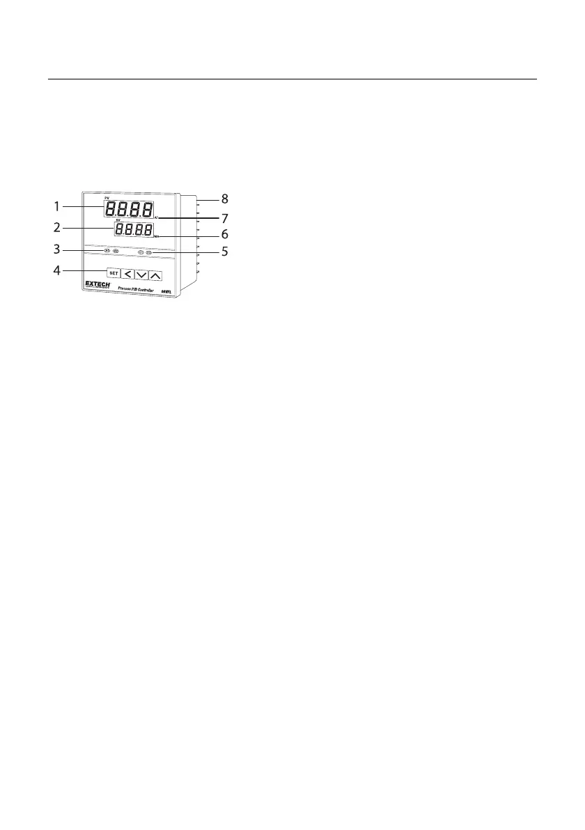
5.1 96VFL Front Panel
FIGURE 5.1: 96VFL FRONT PANEL
1. Process Variable (PV) display digits (red) show the process input.
2. Setting Variable (SV) display digits (green) show the programmed setpoint.
3. Alarm 1 (A1) and Alarm 2 (A2) relay status indicators.
4. Programming keys: Set, Scroll, Down arrow, Up arrow (left to right). See dedicated
section below.
5. Control Output 1 (C1) and Control Output 2 (C2) status indicators.
6. MANUAL control mode status (rightmost decimal flashes on SV display).
7. AUTO TUNING mode status (rightmost decimal flashes on PV display).
8. Connection terminal blocks.