Max300-LG : Description - Specifications - Installation Guide
Extrel
Core Mass Spectrometers
Page 22
.
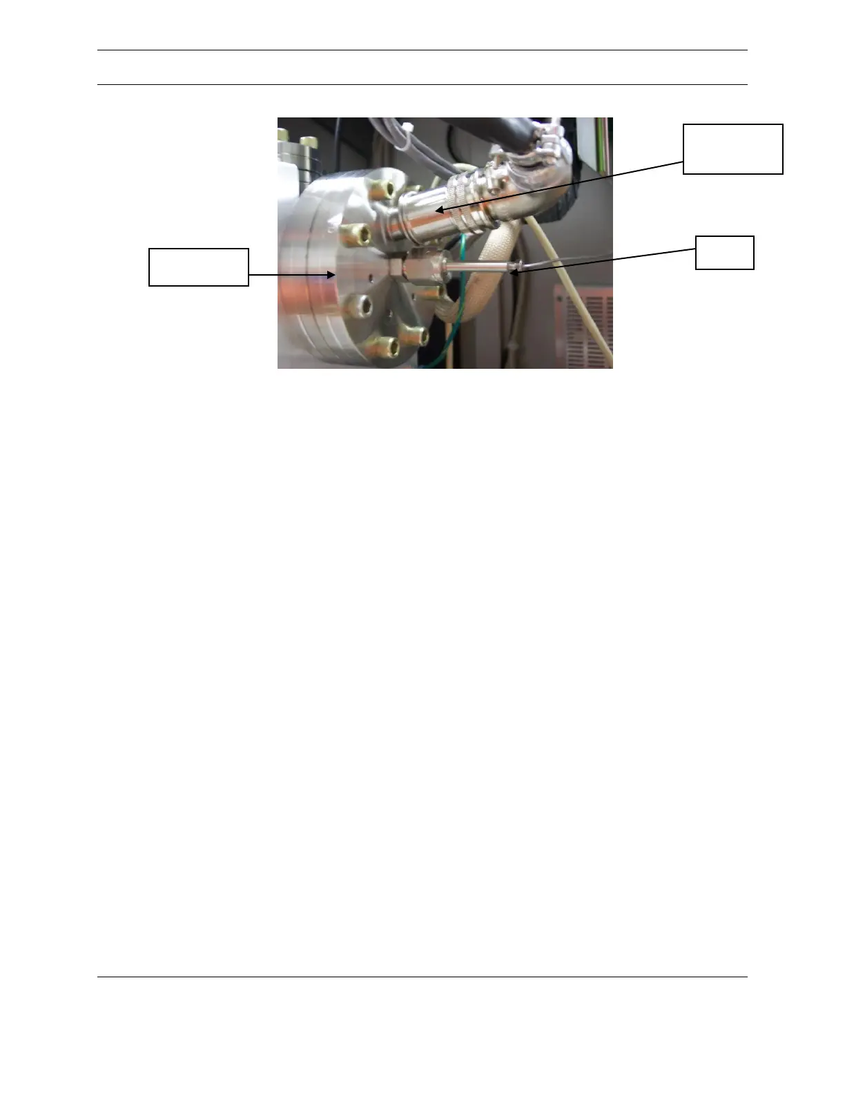
Figure 13: Ionizer flange with Inlet and 10-pin Connector
The ionizer flange is held to the chamber with eight socket head screws (1/4 inch hex
key). Remove the flange and set it on a clean work surface. Remove and discard the
nonreuseable copper gasket.
The ionizer assembly is held in place by spring loaded electrical connections. It can be
removed by grasping the last lens and pulling the module straight from the flange. The
new module is installed by inserting the central ion region into the flange mounted heated
block, aligning the electrical connections and pushing it in place. If the assembly is
properly installed, no gap should be visible between the fixed part of the ionizer block
and the innermost plate of the ionizer. The total height of the assembly can be measured
from the vacuum side of the flange and should be 2.50 inches (63.5 cm). If this
dimension is more than 2.54 inches (64.67 cm), lens 2 will short to the quadrupole rods.
Using a new 4-1/2 inch copper gasket, install the ionizer flange onto the vacuum
chamber. A threaded hole on one side of the electrical feedthrough, visible in Figure 14,
can be used to hold the copper gasket in place. Install the bolts on the flange finger tight.
 Loading...