Max300-LG : Description - Specifications - Installation Guide
Extrel
Core Mass Spectrometers
Page 32
The detector mounting flange can be detached from the vacuum chamber by removing
the securing socket head screws using a 1/4" hex key. Discard the old copper gasket.
Note: Care must be taken when removing this flange to not damage the detector assembly
as the securing screws are removed. Support the flange as the last screw is taken out and
pull the assembly straight back from the vacuum chamber.
The replacement multiplier is a completely assembled multiplier with all the wires
attached and the extended faraday plate installed. Remove the old detector assembly and
install the new one on the flange. Place the detector mounting flange onto a clean level
working surface to begin the replacement procedure.
The electrical connections can be pulled straight off the flange feedthroughs. The
multiplier is held to the flange with two 4-40 screws that can be removed with a 3/32”
hex key.
Install the new multiplier onto the flange in the same orientation as the old one using the
4-40 screws and connect the wires to the flange feedthroughs by pushing the connectors
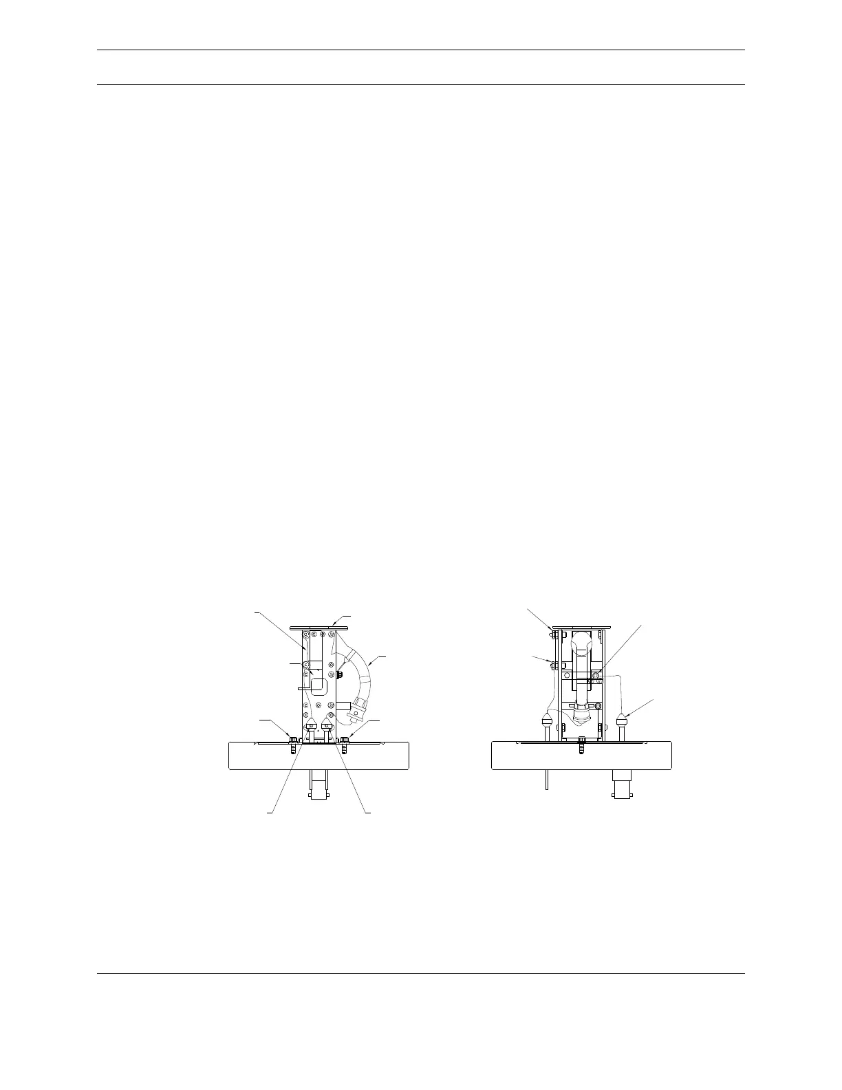
straight on. Refer to Figure 24 to verify that the wiring is correct.
Faraday Connection
Signal Connection
4-40 Securing
Screw
Shorting Strap
FP & CD
High Voltage
Connector
Multiplier
4-40 Securing
Screw
Multiplier Tube
Faraday Plate (FP)
Conversion Dynode
(CD)
FP Connection
Point
CD Connection
Point
Multiplier HV
Connection Point
* Assembly Rotated 90 degrees
* Assembly Reference Illustration
Figure 6.13.2 Multiplier Assembly Detail
Figure 24: Multiplier Flange
Install the detector flange onto the vacuum chamber using a new 4-1/2” copper gasket in
the same orientation it was originally. There are two threaded holes on the flange that can