Hardware Installation
AP-8432 Installation Guide 11
Wall Mount Procedure - New Installation
This section describes a new AP-8432 installation with no previous Access Point existing on
the intended wall surface.
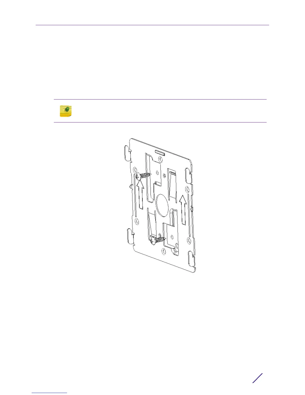
1 Place the mounting bracket against the wall.
2 Mark the screw hole locations depending on the intended deployment orientation of the
unit.
3 At each point, drill a hole in the wall and attach the mounting bracket.
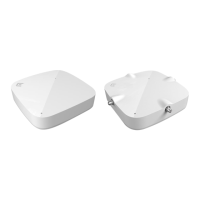
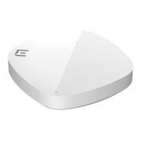
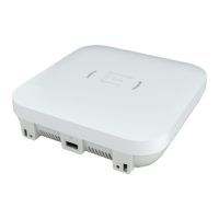
4 Place the Access Point on the mounting bracket.
5 Cable the Access Point using either the Power Injector solution (AP-PSBIAS-2P3-ATR) or
the approved AP-8432 power supply (PWR-BGA48V45W0WW).
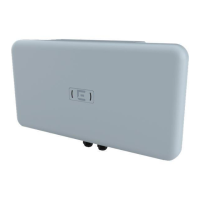
For Power Injector installations:
a Connect a RJ-45 CAT5e (or CAT6) Ethernet cable between the Power Injector
Data &
Power Out
connector and the Access Point’s GE1/POE port.
b Connect a RJ-45 CAT5e (or CAT6) Ethernet cable between the network data supply
(host) and the Power Injector
Data In connector.
c Ensure the cable length from the Ethernet source (host) to the Power Injector and
Access Point does not exceed 100 meters (333 ft). The Power Injector has no On/Off
power switch. The Power Injector receives power as soon as AC power is applied.
For standard power adapter (non Power Injector) and line cord installations:
NOTE
When pre-drilling a hole the recommended hole size is 4mm (0.16in.).
 Loading...