11
3. OPERATION
3-1. Controls, indicators and connectors
3-1-1. FC-7150U, FC-7015U Universal Counter
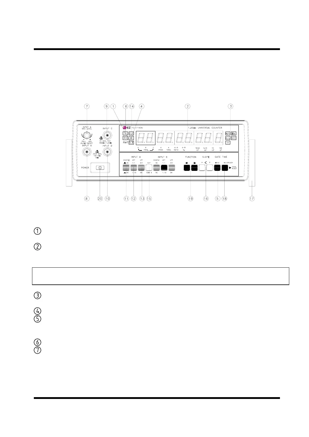
FIG 2. FC-7150U FRONT PANEL
GATE INDICATOR : The gate light, when lit, indicates the main gate is open
and measurement in progress.
DISPLAY : 9 digit(O.56") green LED display used for all read
readings.
NOTE: LAST MEASUREMENT DISPLAY WILL REMAIN FOR 10 SECONDS AFTER
SIGNAL OFF.
UNIT INDICATOR : When lit, indicates that the frequency displayed is in KHz
or MHz, and period is in n, u or mSec.
HOLD INDICATOR : When lit, engaged the hold function.
HOLD SWITCH : In hold function the display held but the counters
continue to increment. When the hold is released, the
display is updated and resumes counting.
RS-232C INDICATOR : TX(transmitting), RX(receiving) blinking(OPTION)
TRIG. LEVEL VR : Adjusts trigger threshold level on the input A input signal.
Pushing the knob in (preset) sets this level at the mid-
point of a symmetrical sinewave input. Pulling the knob
out and rotating it varies the level from negative to
positive around the mid point.
Test Equipment Depot - 800.517.8431 - 99 Washington Street Melrose, MA 02176
FAX 781.665.0780 - TestEquipmentDepot.com


 To Next Page