13
Negative going edge of each signal is selected By the slope switches.
g. RATIO (A/B). When this mode is selected, the unit measures the ratio of input A
frequency to the input B frequency.
POWER SWITCH : Push in the unit ON and push out the unit power OFF.
115V 230V
115V
230V
SN :
VOLTAGE POWER MAX
0.5AF
0.25AF
FUSE
10W
10W
2
54
16
3
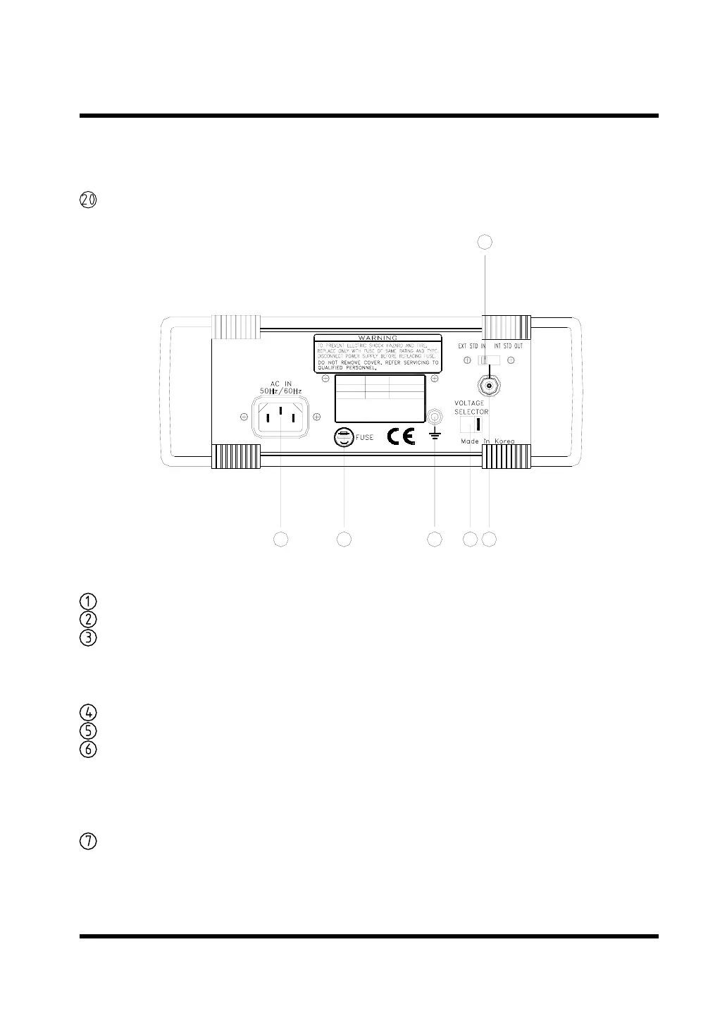
FIG 3.
FC-7150U/FC-7015U REAR PANEL
VOLTAGE SELECTOR : Select ac power, 115V AC or 230V AC.
AC INLET :For connecting of the supplied ac power
INT/EXT TIME BASE SELECTOR : Select the time base, switch position
EXT. STD.IN provides a nominal 600Ω input impedance
path for an external 10 MHz time base. switch position
INT. STD.OUT monitors the internal time base signal.
GROUND TERMINAL
FUSE HOLDER :Replacing fuse with unscrewing
INT/EXT TIME BASE BNC: Serves as a monitoring point for the internal time
base signal, or provides an input path for an external
time base signal depending on the INT/EXT switch setting.
The external signal should have a voltage range of
1.5V~5 Vrms.
RS-232C CONNECTOR : Connector for serial interfacing with computer.
Test Equipment Depot - 800.517.8431 - 99 Washington Street Melrose, MA 02176
FAX 781.665.0780 - TestEquipmentDepot.com
 Loading...