3
455 D Control Board
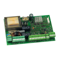
Figure B
1.4. 455 D Layout and Components
NB: Capacitors are supplied with the operator.
Important: Before attempting any work on the control
board (connections, maintenance), always turn off
power.
1. 455 D CONTROL BOARD
1.3 Electric Connections
J4
J1
J3
F1
F2
PE N
L
MAIN
12 45678
COM
OP
M1
COM
OP
M2
CL
LAMP
910111213141516171819
OPEN
AB
STP
CL
OP
FSW
---
+24V
++
-TX
FSW
20 21
W.L.
LOCK
J5
J2
F
22
23
24 25
FCA1
FCC1
FCA2
FCC2
–
+
STOP
OP_A
OP_B
FSWCL
FSWOP
FCC1
FCC2
FCA1
FCA2
J6
Figure A
F
F1
F2
J1
J2
J3
J4
J5
J6
DL
–
+
Power Supply 115 V~ ± 10% or 230 V~ +6% -10% 50/60 Hz
Absorbed Power 10 W
Motor Max. Load 800 W
Accessories Max. Load 0,5 A
Electric Lock Max. Load 15 VA
Ambient Operating Temperature Range -4°F to +131°F
Protection Fuses 2 (see Fig. A)
Function Logics: Semi-automatic / Automatic / Safety Devices /
“Stepped” Semi-automatic / “Stepped” Automatic / “Stepped” Safety
Devices / Semi-automatic B / Dead-man C
Opening/Closing Time Programmable (from 0 to 120 s)
Pause Time Programmable (from 0 to 4 min.)
Closing Leaf Delay Programmable (from 0 to 4 min.)
Opening Leaf Delay 2 s (can be excluded)
Thrust Force: Adjustable on 50 levels for each motor
Terminal Board Inputs: Open / Open Free Leaf / Stop / Limit-switch
Opening Safety Devices / Closing Safety Devices / Power Supply +
Earth.
Terminal Board Outputs: Flashing Lamp / Motors / 24 VDC Acces-
sories Power Supply / 24 VDC Indicator-Light / Fail Safe / 12 VAC
Electric Lock Power Supply
Programmable Functions: Logic / Pause Time / Thrust Force / Torque
at Initial Thrust / Opening and Closing Leaf Delay / Reversing Stroke
/ Over-Pushing Stroke / Indicator-Light / Pre-Flashing / Electric Lock /
Fail Safe / Safety Devices Logic / Assistance Request / Detection Time
of Obstacle or Contact Point
Learning Function: Simple or complete work time learning, with or
without Limit-switch and/or Gatecoder.
1.2. Technical Specications
1.1 455 D Control Board Warnings
Please refer to Chapter 16 for AC power wiring
guidelines
DL SIGNALLING AND PROGRAMMING DISPLAY
J1 LOW VOLTAGE TERMINAL BLOCK
J2 CONNECTOR FOR RP RECEIVER
J3 AC POWER SUPPLY TERMINAL BLOCK
J4 MOTORS AND FLASHING LAMP CONNECTION TERMINAL BLOCK
J5 INDICATOR-LIGHT AND ELECTRIC LOCK TERMINAL BLOCK
J6 LIMIT-SWITCH AND GATECODER TERMINAL BLOCK
F1 MOTORS AND TRANSFORMER PRIMARY WINDING
FUSE (F 5A - 230V) (F 10A - 115V)
F2 LOW VOLTAGE AND ACCESSORIES FUSE (T 800mA)
F “F” PROGRAMMING PUSH-BUTTON
– “–” PROGRAMMING PUSH-BUTTON
+ “+” PROGRAMMING PUSH-BUTTON
24 VDC
3W
12 VAC
FCC2
LIMIT-SWITCH
OR GATECODER
230 VAC
50 Hz
or
115 VAC
60 Hz
VAC MAX.
60W
OPEN A
OPEN B
STOP
BLUE
BLUE
For connection
of the photo-
cells and safety
devices, see
Section 13.4.1.